This is follow up to my previous post about building a Martin Eberhard 1702/A EPROM programmer.
In this post, I will share some more details about this project. This is not a kit, but Martin occasionally sells a PCB with a programmed PIC micro controller. Extensive instructions, including a parts list with recommend suppliers can be downloaded. Martin has sold several batches of these PCBs over the last couple of years, and I purchased a PCB and PIC from his most recent batch.
The programmer has a built in RS232 interface and can be controlled by any computer with terminal emulation software that supports capturing text to a file and sending text files. I use CoolTerm on a Macintosh for this functionality
All the parts have either Allied or Digikey parts numbers, so it is a pretty simple process of ordering your parts using Martin’s bill of materials. In my case, I found that I had some of the more vanilla parts already on hand, and I saved a few bucks by using what I already had. There are quite a number of different parts required. Usually when I order parts, I order spares of everything, but in this case, I ordered exact quantities of most parts, as I figured paying the postage for one or two damaged parts would be cheaper than ordering spares. In my initial order, I forgot to order one part and didn’t order enough quanity of a second part. These were my mistakes, as Martin’s bill of materials are right on.
I also made a couple of substitutions, one that didn’t work out so well. In the case of the DB-9, I purchased a male connecter instead of female. This is because most of my other devices with DB-9’s, use male connectors and this would allow me to use existing cables. In the case of the MAX232, I substituted a MAX202. The MAX202 has the same pinout as the MAX232, but uses .1uF capacitors. I had both the MAX202 and .1uF capacitors on hand, so this was a no brainer substitution.
The one that didn’t work out so perfectly, was the power supply plug, the Apple 1 uses the same form factor .156″ 6 pin header, so I used a connector from my stash of Apple 1 parts. Unfortunately the Apple 1 is a slightly different style, so the pins I bought, using the 1702/A BOM were not correct for the Apple 1 connector. I would have used Apple 1 pins, but I was out of them. I should have refered to my Apple 1 BOM in order to get the correct pins for my connectors. I was able to make do with the combination of connector and pins, but it’s not as secure as it should be. For now I have used silicon glue to secure the connecters to the housing. Next time I put in an order, I’ll get the correct connector and fix this issue.
I only have three colors of 18 gauge wire, so my color coding is not optimal. I used black for black, red for white and green for everything else. For the wires that go to multiple locations, I recommend running a pigtail and connecting multiple wires to the pigtail and covering the connection with heat shrink tubing.
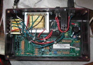
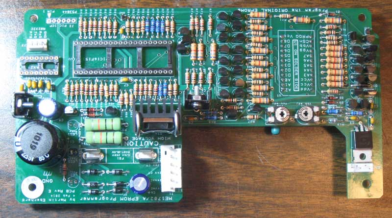
Inside ME 1702/a Programmer
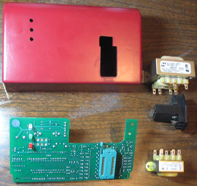
Cutting the case openings was pretty time consuming. I made the cut outs by drilling holes in the corners of each cut out using the template from the manual. I then used a coping saw to connect each hole. This was followed by a lot of hand filing and tweaking with a dremel type tool with a cut off wheel attachment. The cut off wheel really helped me keep the straight edges, straight. Keeping edges straight would have been much more difficult with a regular grinding bit. For my first round of 1702 programming, I had borrowed a unit that had been painted MITS blue. That looked pretty nice, so I had to fill the sprue location in the front of my chassis and slap some paint on it. I’d guess that an expert could do it faster and better, and the paint job is pretty crusty, but I’m fairly happy with the result. I’m considering improving the paint job and making some decals or screen printing the chassis with a logo and lettering in the future.
One of the more time consuming parts of this project was wiring the transformers. Anyone that has done an Apple 1, will immediately recognize what is going on and be able to figure it out. During assembly, I made one mistake, and that was wiring the six pin .156″ power connector. That caused a blown fuse, but apparently no other damage. Make sure you know which end of that connector is pin 1 – the description is clear in the manual, but I guess I didn’t read it closely enough.
The instructions include rather detailed checkout instructions, and I recommend following them. My unit has two voltages that are a bit higher then specified in the manual. The first was found during Step 10, “Test High-Voltage Power Supply Control”. The voltage on the right side of R95 was just a shade over 75 volts. It is supposed be the combination of the drop over two zeners, 15 and 58 volts, which should have made the result about 73 volts. In my system, the drop over the 58 volt, 4758 volt zener, was just over 60 volts. This added to the 15 volt drop of the other zener resulted in the >75 volt reading. It could be that zener was out of spec, but I decided that it was probably close enough and moved on.
The other slightly high voltage was found in step 14, “Test High-Voltage Logic Signals”, where I found that logic low on the data signals was around .84 volts, when the manual said it should be under .7 volts. I looked at the schematics and measured voltages at several points in that circuit and couldn’t find any obvious issue. Looking at the 1702 spec, it looks like programming data low is -46 to -48 volts. Since the supply is 48 volts, that gives 2 volts of margin, so it should be fine. I decided to move ahead and try programming some actual devices.
I started with a part that probably had a burned out data bit. I did a number of experiments and could read the part and program each bit (except the bad one) and address successfully. Then I moved onto another part and proved out the bit I couldn’t test with the first part.
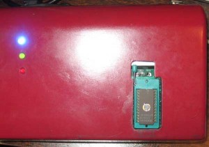
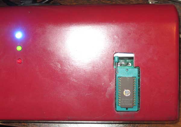
ME 1702/A Programmer
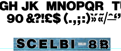
My Martin Eberhard 1702/A programmer appears to be working perfectly. I don’t have much mileage on this newly built 1702A programmer, but I can comment on the experience of using my friends, a few months back. At the time, I needed to program 16 devices for the SCELBI PROM board. I had very few issues during that session. I found two parts that didn’t blank check. Since I don’t yet have an erasing light, I don’t know if these parts are bad or just have been programmed before they got to me. I was able to program 16 parts that did blank check correctly with only one hiccup. That was one part that apparently hung the programmer, or was just taking a very long time to program. I power cycled and repeated the operation with the same part and it completed normally. I’m very impressed with this programmer, as well as the reliability of the 40 year old NOS 1702 EPROMs that I have had such good luck with.
Looking forward, I now have the capability to program the SCELBI keyboard and oscilloscope interfaces without having to borrow friends equipment. I expect I’ll have to go through several iterations of those drivers, since we haven’t found the original SCELBI software. I’m interested to find how these old devices will stand up to reprogramming.
I consider that building this programmer a medium sized project. Except for my own projects, I haven’t built any micro-controller based kits before. This one was really fun. I wouldn’t recommend it for a beginner, but someone who has been restoring or reproducing 70’s era computer systems for a while should have a lot of fun building this very useful device.
The cost will vary depending upon what you can find in your stash, but I think you should be able to build one of these units for $160-$180.


