Here is where this document really looks more like a product plan more than anything else. This section starts with a statement of availability of prototypes on March ’74 and production unit in June ’74. It follows with statements that no field service will be offered and a warranty period of 90 days. The lack of field service is due to the expectation that the customer will be technically capable, the relatively low cost of the product and high cost of field service contracts.
The next page contains a product promotion and support plan. It mentions several trade magazines, was well as a direct mail campaign. I checked several of the periodicals mentioned and couldn’t find any relevant MPS-10 ads, so I don’t know if they came out later or exactly what happened.
The documentation plan is mentioned, as well as some trade shows.
Given this extensive marketing plan, it is somewhat surprising that so little is known of the MPS-10 today.
The competition section might be the most interesting to vintage computer hobbyist. Among other architectures, the National IMP16 series is mentioned. The IMP16 is classified as a microprogrammed machine, rather than a fixed instruction set, as the 8008 and 8080 and a few others are classified as.
On the next page are listed a number of competitive systems made up from the previously listed microprocessors. Except for the the Microl and Sim-8, most of these systems are little known by the vintage computer hobbyist of today.
There is a chart showing features of the various systems, including the all important development tool support. This section is definitely worth review by the vintage computer hobbyist.
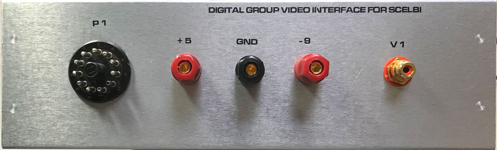
Front of Digital Group Video Card Enclosure for SCELBI
The lettering on the front is made with water slide decals printed with a laser printer. After applying, several coats of satin lacquer were sprayed on to protect the lettering.
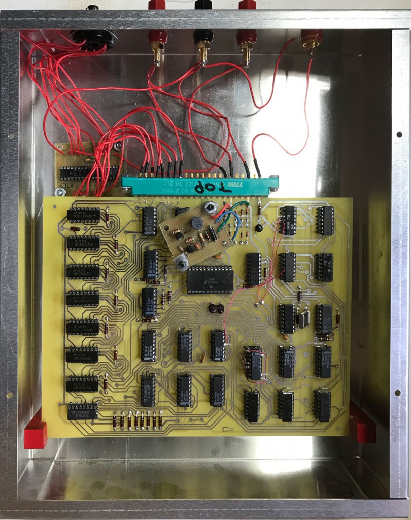
Inside Digital Group Video Card Enclosure for SCELBI
There is only one edge connector for this double wide card. I decided this wasn’t enough support so I added those red blocks seen towards the bottom of this image. The small card on the upper left hand corner is used to latch the SCELBI output.
In a way, this is a project that doesn’t want to end. I still have to get some kind of demo application going and update my OS/X emulator to support this card. I’ll probably do the later, first, as it is easier to debug with the emulator than on the real system.
The page on performance starts by with a quick outline of the capabilities of an 8008 microprocessor. It then details timing of handling interrupts, the UART and external events.
The software page outlines some more of the basic implementation of the 8008, and outlines available tools. The user is expected to use a teletype and a PDP-8 during software development. There is a loader program that will reside in the M7342 Monitor/Control Module ROM.
The diagnostic page highlights available diagnostic capability of the MPS-10 which include PROM and RAM based diagnostics. There is also a section that specifies documentation that will be available. There will be both a hardware and software section in the user documentation.
The final part of this section includes note that says data sheets and product brochures will be available. This section seems just like a program plan, rather than end user documentation.
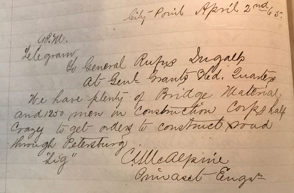
Here’s a telegram written by the Head Engineer of the Military Railroad at City Point to Rufus Ingalls, Chief Quartermaster of the Armies before Richmond.
To General Rufus Ingalls, At Genl. Grants Head Quarters We have plenty of Bridge Material and 1250 men in Construction Corps half Crazy to get orders to construct road through Petersburg. C S McAlpine, ——– Engineer
This message was sent on the same day that the Union Armies broke through the Confederate lines just south of Petersburg.
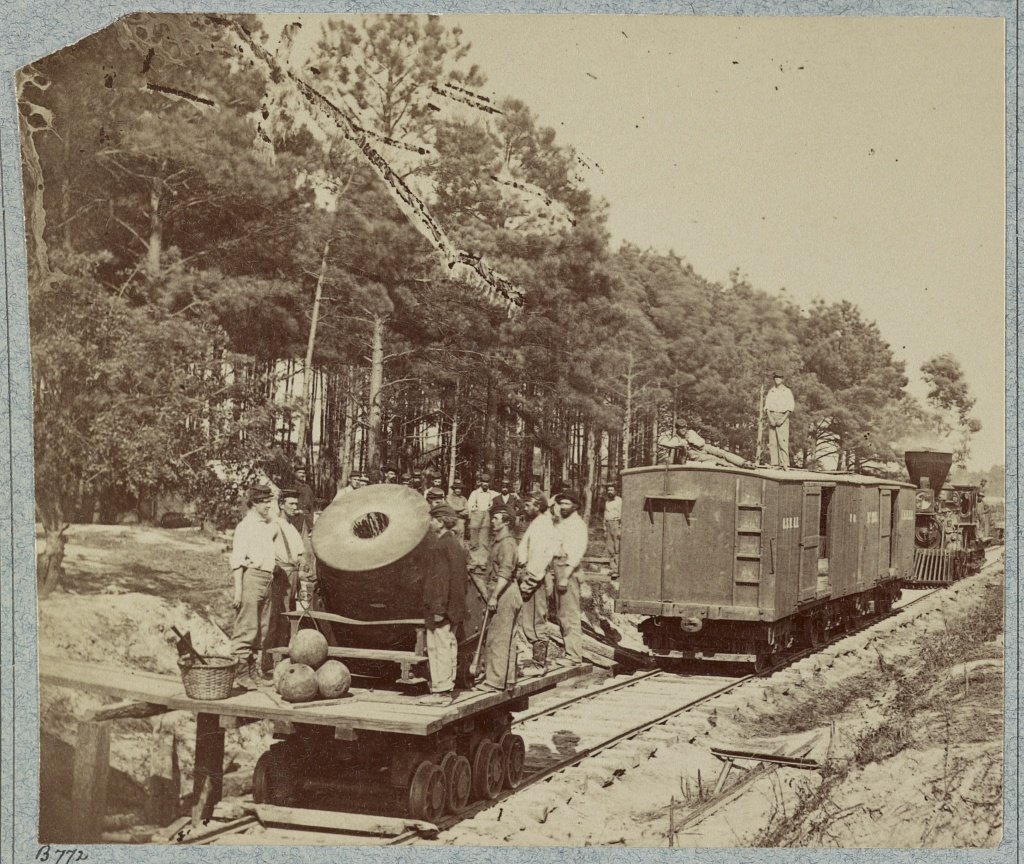
The Dictator was a 13 inch siege mortar used to bombard Confederate positions around Petersburg in the summer of 1864. It was mounted on a specially constructed flatcar so it could be moved around easily. It was initially used to silence a Confederate artillery position across the Appomattox River from the Union right. Until this position was silenced, the Confederate artillery enfiladed the right end of the Union line and made life especially difficult for the Union troops stationed in the trenches there. The Dictator was pulled out of the front line service on September 28, 1864 and put in reserve at the base at City Point.
The Mortar Dictator in front of Petersburg
However that isn’t quite the end of the story. This letter found in the National Archives indicates that as late as December 4th, 1864, some men, which came from the 1st Connecticut Heavy Artillery regiment were still watching over her.
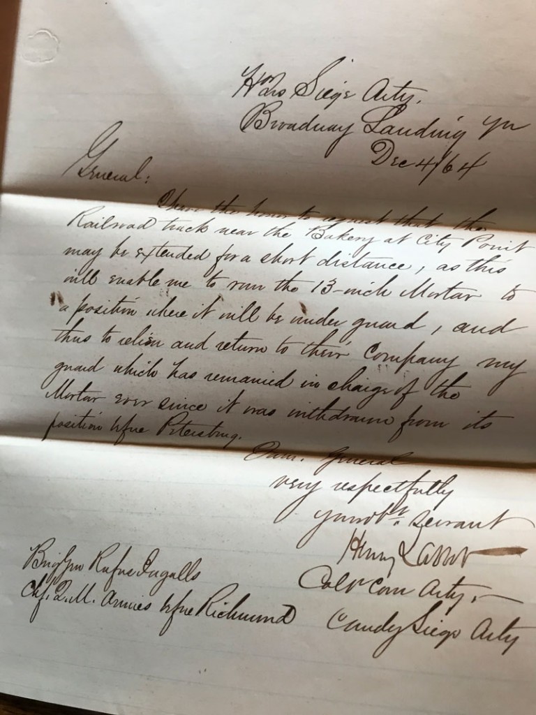
Mortar Guards Letter
Here is the text of this letter to Rufus Ingalls, who was the Chief Quartermaster for all the Armies before Richmond..
Headqua. Siege Arty. Broadway Landing
Dec 4th, 64
I have the honor to request that the Railroad track near the Bakery at City Point may be extended for a short distance, as this will enable me to move the 13-inch Mortar to a position where it will be under guard, and thus to relieve and return to their Company my guard which has remained in charge of the Mortar ever since it was withdrawn from it’s position in front of Petersburg
very respectfully Your ob. servant Henry Larcom Col. Conn. Arty. Commander Siege Arty.
Note that E.L. Henry’s painting of City Point shows the Dictator positioned in an altogether different location, at the end of the tracks serving the Quatermaster Department Wharves. It likely that this is where the Colonel’s men were spending their time watching her. Note that Henry even painted a guard next to the mortar.
Dictator at City Point
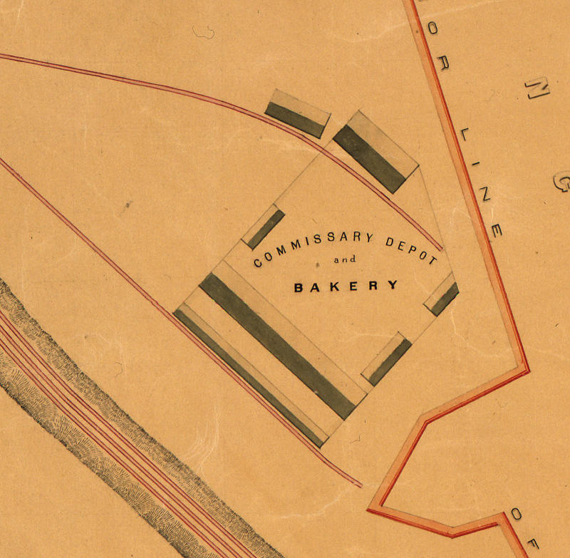
Looking at the map of the City Point railway, which was drawn after the war, shows that the bakery tracks do extend a bit past the end of the bakery buildings. It’s clear that if the Dictator was positioned there, it could be guarded by the men manning the City Point defensive line. Whether this is the extension that was requested or not and whether the Dictator ever ended up at this extension of the bakery tracks is unknown to me.
City Point Bakery
Though this little investigation of mine has little importance to anything or anyone, it is fun to see what can be found out about such trivial issues.
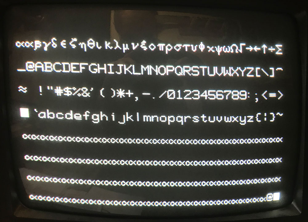
In an addendum to my previous post, I noted that I had MCM6571A instead of regular MCM6571. It seems like the A part is easier to find than the regular part, so I decided to hack the board to support the A part, while I look around for a non-A part. Here’s an example of the resulting video output after the hack.
DG Good Video
These parts have the same character set, but the row decoding goes up from 0 to 8 on the A part instead of from 14 down to 6 on the regular part.
Fortunately, on the DG video card, row input to the MCM6571 is entirely from the four outputs from the 74193 at U9. The 74193 supports counting down or up as well as configurable preloads. So all you need to do to support the “A” part is count up instead of down and reconfigure the preload, preload trigger and carry out to the next 74193. This can all be done without extra gates.
The standard DG card counts down from 15 to 2 and then restarts the count using the gate at U-22. To make the circuit work for the “A” part, I choose to reconfigure the counter to count up from 0 to 12. This is one less sweep of horizontal per line of characters, but it doesn’t seems to affect vertical hold on the terminal that I am using and it prevents the last line of text from being too “low” on the screen and puts the lines a little closer together for a slightly more pleasing display.
The carry over to U-10 occurs on the rising edge of the most significant bit of the the counter. This happens when the count goes from 2 (binary 0010) to start over at 15 (binary 1111). To make the circuit work for the “A” part, I choose to use the inverted version of the most significant bit, so it carries over when the output goes from 12 (1100) to 0 (0000).
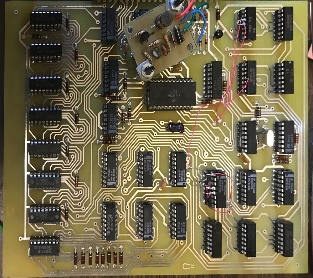
Here is the wiring list needed to make this change. I choose to put the 74193 in an extra socket to make the rework easier. The way I made this change, it is completely reversible and requires no cuts to the PCB, so when I find a non-A part, I’ll be able to retrofit it to this board with minimal effort.
DG Video 6571A Hack
Remove the 74193 at U9 from the PCB and insert into a spare 16 pin socket with the following legs lifted:1,4,5,9,10,15
the following two steps change count down function to count up
Connect pin 4 of the 74193 to the socket pin 5
Connect pin 5 of the 74193 to the socket pin 4
the following step changes the preset from 1111 to 0000
Connect pins 1,9,10,15 of the 74193 to the socket pin 8
the following two steps changes the reset from a value to 2 to a value of 12
On the 7410 at U-22 lift pins 9 and 10
Connect pin 9 of the 7410 at U22 to U9, pin 7 (it can be connected to a convenient via near the MCM6571 that leads to U9, pin7)
Connect pin 10 of the 7410 at U22 to U9, pin 6 (it can be connected to a convenient via near the MCM6571 that leads to U9, pin6)
the last step inverts the carry input to the 74193 counter at U10
Lift U10, pin 5
Connect pin 5 of the 74193 at U10 to U17, pin4
Now all I need to do is to get some kind of demo application running and update my Macintosh SCELBI app to support emulation of this new SCELBI capability.
If anyone wants one of these reproduction DG video boards, cost will be $50 each, with free shipping in USA, $10 shipping outside the USA. Send me an email if you are interested.
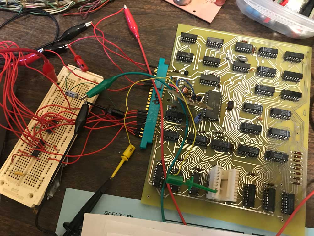
I’m making some progress on the Digital Group video card debug, but it has been a bit more difficult than I expected. First I had to connect it to my SCELBI and write a short program to test it with. Here is the test setup.
DG Video Test Rig
I needed to add an 8 bit latch in order to latch the SCELBI output port. This was easily accomplished with 2 7475 four bit latches and a bread board that I had in my parts bin. If I was thinking ahead, I would have added it to the PCB that contains the +5 volt to + 12 volt converter. Now I’m going to have to add another board to the final chassis design in order to hold the 8 bit latch.
The 5 volt to 12 volt converter is resulting in 11.96 volts at the MCM6571. That is nearly spot on, so it looks like that effort has paid off. One other thing to keep in mind when wiring the power for peripherals on the SCELBI, it’s pretty important to avoid ground loops and run power and ground directly back to the power supply. It’s tempting to use the ground wire on the peripheral cable, but it’s best not to do that.
Debug has been a bit slow, and I found a couple of assembly mistakes on the PCB. First, I put capacitor C8 in the wrong holes which caused problems with the R/W output of U-23. The second mistake was forgetting to solder the ground pin of the 6571 character generator. I also had a bad 74193 in the circuit that was used for writing to video memory. In this build, I used sockets, so testing and replacing the 74193 was pretty easy.
The documentation suggests that a user could use a second output port and directly address video memory, rather than use the counter solution. Given that there usually is no shortage of output ports on the SCELBI, this might make a better solution for the SCELBI. It would be fairly simple to replace the two 74193 counters with 7475 latches in order to achieve this.
During this process I wrote two short programs for debug. The first one puts the same character in every location in memory. This was helpful when I was having trouble writing to memory. Putting the same data in every location made it easier to tell whether writes to the 1101 memory were working or not.
These programs were both short enough that I just toggle them in through the front panel, rather than worry about setting up a TTY or scope and run MEA or MCMON.
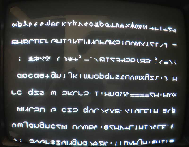
The display with the second program loading up memory with a range of characters currently looks like this:
DG Video Output
So the good news is that the horizontal and vertical sync is looking pretty good. In fact, given my concerns about the PCB layout, the video is downright crisp, much better than the Apple 1 or Apple []. I’m pretty impressed. The bad news is that the characters are all displayed upside down and clipped at the bottom. I’ll have to figure that out in my next debug session.
UPDATE: I just figured out that my reversed character problem is that I’m using a MCM6571A part which has a different/reversed decode when compared to a regular MCM6571. With character generators, you have to be careful about versions of the part and I guess I didn’t pay enough attention in this case.
Although this 8008 system has a feature set that is similar to other 8008 computers, there are some differences that make this system unusual.
Memory support for the MPS10 is typical of other 8008 systems, with from 1k to 16K of memory. The SRAM module used 2102 type memories and the EPROM card took up to 16 1702A EPROM chips.
One of the unusual features is the UART incorporated into the main CPU card. The UART supports a full duplex serial interface.
The main processor board also has a berg connector intended to interconnect with the Monitor/Control module with a “standard cable”. The Monitor/Control Module is mounted in it’s own cabinet, outside the M-series chassis that holds the rest of this system. The monitor and control module was intended for maintenance and program debug only. It supports typical debug operations such as read and write memory, running, stopping and stepping programs. It also contains a ROM with bootstrap program.
Finally, the MPS10 included an External Event Detection Module (EEDM) which supported up to 8 external interrupts and a power fail detection circuit. I’d say the extra external interrupt support was added because of the vision of using this system in process control applications and the weakness of the 8008 regarding interrupt handling capability.
Also mentioned is the foundation module, which is supposed to support user hardware interfacing. I don’t know much about the DEC “M” series chassis, but it appears that these foundation modules are some sort of standard prototyping boards, that were already being sold by DEC.
There is a paragraph discussing how to evaluate micro-processors, which is basically the same as evaluating any computer. The next section asks why use the Intel chip – the answer being that it’s about the only one available. Perhaps at the time that it was written, the IMP-16 wasn’t known about or available or the IMP-16 was dismissed for other reasons.
The next section starts discussing the MPS10. One thing that is called out, is that the MPS10 is a member of DECs M series module line. I don’t know anything about the M series modules, but perhaps some existing M series modules would be able to interoperate with the MPS10.
The next section lists the five modules that make up the MPS processor system. These modules are:
The M7341 processor module
The M7342 monitor/control module
Three size variations of the M7344 Memory module (1K, 2K, 4K)
The M7345 4K Prom memory module
The m7346 external event detection module
The last part of this section discusses the relationship of the MPS10 with other Digital Equipment Corporation Computers. The first statement of this section states that the MPS10 is not a minicomputer and is not intended to compete with minicomputers. It was designed to be a dedicated controller, a replacement for fixed logic designs.
“It should be considered to be an extremely useful augmentation of and addition to, DEC’s existing arsenal of processing devices.”
One thing to keep in mind, is that DEC had a very successful line of minicomputers, and undercutting that business from within the company, would have been a very risky proposition. Any change of architecture away from the PDP series would leave a potential customer, the option of evaluating systems from competing businesses as well as any new DEC architecture. The developers of the MPS10 had to be careful to not threaten the existing DEC business, which could account for some of the language in this document.
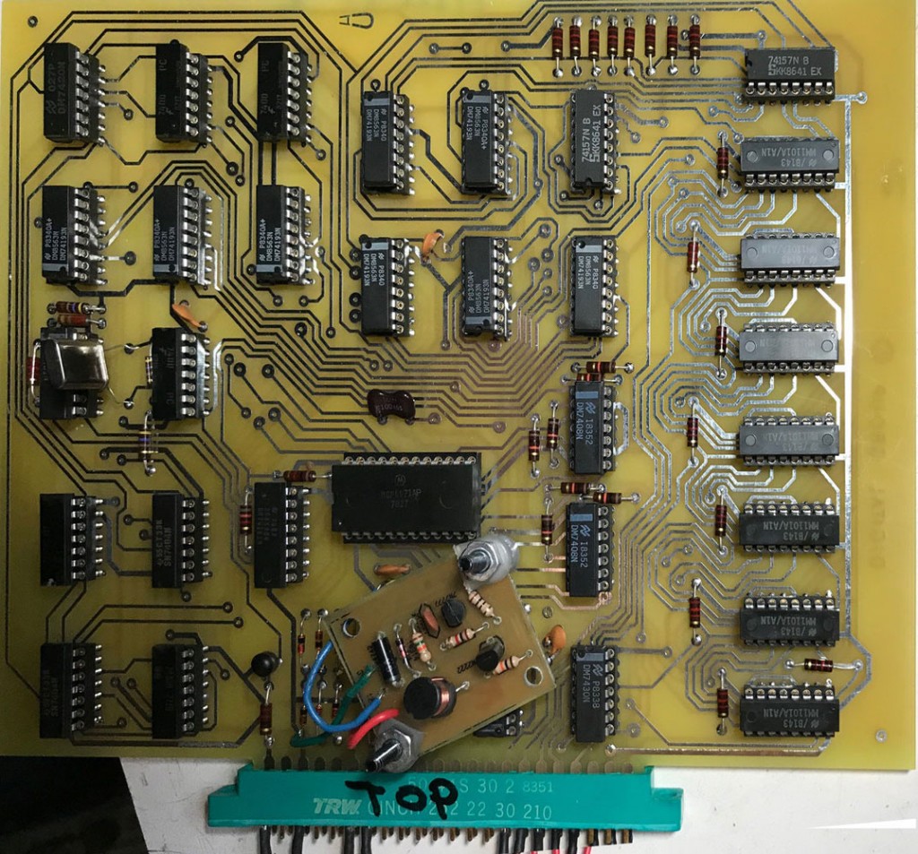
So far, I’ve tested power rails and they appear to be reasonably good. The SCELBI power supplies provide +5 and -9. In addition, components on this card need -5 and +12. The -5 is generated on board using a series of voltage dropping diodes connected to the -9 supply. The +12 is generated with the little converter that can be seen mounted on top of the board. That converter has been documented in a few previous posts. The -5 supply sits at something like 5.6, which is a bit on the high side, but I’ll just go with it. The +12 looks pretty good, as it is sitting at 11.8. Voltages could change a little bit in actual operation as the testing was done without a running clock. I’ll definitely keep an eye on that as I move forward with more testing.
Reproduction DG Video Card
I am expecting the crystal that I need to arrive next week. The installed crystal is something I had on hand in a parts bin. It is something like 3.6 Mhz, which I figured is close enough that I could use it to check clock generation and general performance of the timing portions of the circuit.