The next section of this MPS10 document contains information about recommended applications.
http://www.willegal.net/blog/wp-content/uploads/2019/10/MPS-10-applications.pdf
The main thing to take away from this section is the first point. The end user is envisioned as a “OEM or large end user (corporate OEM)“. Though, it is also envisioned as going into “extremely price-sensitive” applications, the MPS10 was not envisioned as a home or hobbyist machine or even applicable to small businesses.
I think that this is typical of many currently mis-understood early micro-processor based systems. The companies manufacturing these systems didn’t really want to be bothered by small one-off end users, who might end up requiring a very large amount of support for very few or even single sales. The vendors of many systems like the MPS10 were looking for volume sales opportunities, because they knew that tools and support infrastructure was very limited in scope. In this case, DEC was looking for sales to tech savvy companies that could work through most of the technical issues on their own. This is clearly called out in the statement: “Is hardware-design-oriented and has in-house technical capability”.
A similar comment can be found on page 66 of the Micral user’s manual.
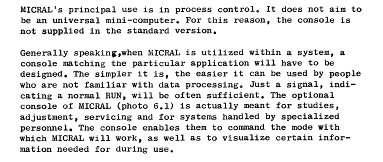
Most companies selling these early, very primitive, microprocessor based computers were looking for tech savvy companies to buy the computers and embed them in end-user applications.
The next section of the document list possible applications that this system may be used for. These days, every one of these suggested applications would be classified as a embedded systems application. The last part of this section list a couple specific embedded applications. The first one, a process control application, includes a flow chart that fits on one page. This should give the reader a good idea of what kind of application was deemed suitable for the MPS10 microcomputer. There is absolutely no mention of hobby or learning type applications in this document.
The first small SCELBI ad contained a vastly different message, “DESIGNED FOR THE ELECTRONIC/COMPUTER HOBBYIST!”. What really made the SCELBI, MARK-8 and similar systems so different than regular computers of the time was the marketing.