Lunar Lander for SCELBI and is there a “Solution”?

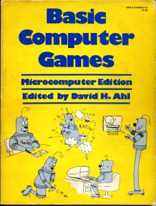
While putting the finishing touches on a new version of my OS/X SCELBI app, I spent some time porting over the classic Lunar Lander game program to SCELBAL. I started with the version from a 1978 edition of “BASIC Computer Games” by David H. Ahl. I bought my edition of that book back in 1978, along with my Apple II.

BASIC Computer Games

BASIC Computer Games

I remember trying to type in a game from this book, the first night that I had the Apple II, only to almost immediately run out of memory. I initially purchased a 4K Apple II system, and only about 2K was usable by BASIC, so it didn’t take much to exceed it’s memory capacity.

Anyway, back to the present. I found porting Lander to SCELBAL was pretty easy. I had two issues.

  • First was an issue with the calculations exceeding the 6 digits of precision supported by SCELBI floating point, which caused a math error. This was fixed by changing the compare instruction at line 340 to IF S <5E-1 THEN 260 instead of S<5E-3 then 260, which reduced the amount of precision required.
  • The second issue is that SCELBI doesn’t support multiple statements on one line, which was easily rectified.
  • While working on this, I wondered if there was a single number solution for Lunar Lander. Using a simple binary search mechanism and multiple copies of the SCELBI app, I was able to determine that with 6 digits of precision allowed by SCELBAL that there isn’t a single number that can be entered every time and result in a safe landing. The closest I could get is a burn rate of 76.4386, which results in a crater only 33.83179 feet deep. Entering a number of 76.4387 results in an out of fuel situation, as the lander just misses landing before proceeding to accelerate upward after which it runs out of fuel and then comes crashing back down.

    As far as releasing an updated SCELBI app, it is in pretty good shape and I should be releasing it within the next week. I’ve taken advantage of a holiday break from work in order to make significant improvements and revisions and I think this version will be a vast improvement over the last release.

    Oh and here is a link to the ported version of Lunar Lander.

    Where Did My Neighborhood Bats Go?

    One evening last summer, during an evening party, I got out my bat detector. Much to my surprise, I was unable to detect any bats. This struck me as very odd, since during previous summers, I never had any difficulty detecting plenty of bats. Well, I just found out what happened to my neighborhood bats. There is a disease, known as White Nose Syndrome, attacking colonies of bats throughout the world. In many cases, bat populations have plumeted, with some species facing possible extinction.

    The real question I have, is, with such a disasterous decline in bat populations, why didn’t news of this reach me through regular news channels. I only discovered the problem, when I stumbled upon the story when I looked on the web for a link to the instructions I used to build my bat detector.

    I’ve been thinking for some time that major English language news agencys have a narrow focus on a few topics, instead of covering a broad range of news. That millions of bats could die, some literally in my back yard, and that the news agencys leave me unaware seems almost criminal. Instead, we get bombarded with the news about a few wacko’s killing inocent people who happen to be in the wrong place at the wrong time.

    Maybe, due to high costs and tremendous competition, the major news agencies are limiting news to what they can sell, not what an editor thinks we need to know. It seems, at least at major news agencies, the role of that editor, the person that promoted a point of view, has been replaced by a marketing person. To me, it’s a shame.

    New Version 2.2 of SCELBI OS/X Emulator Posted

    I’m really excited to be able to release version 2.2 because of it’s capabilities. After several years of on and off effort, this version is good enough to completely support all the features of MEA, SCELBI’s 8008 software development environment.

    You should be able to develop and test 8008 applications without ever leaving this application. In addition, the audio files it reads and writes are completely compatible with the actual SCELBI cassette tape interface hardware. This means that you can transfer object and source files back and forth to real SCELBI hardware with ease.

    Read more about it on this webpage

    The MEA manual can be downloaded from scelbi.com.

    Instructions for operating the front panel, which is necessary to boot MEA can also be found at scelbi.com.

    To start MEA, you must toggle a JUMP to location 060-000 with the front panel.

    Can -47dB be equal to 60dB?

    dB is usually used as a relative measure of power, so it all depends upon if the dB value on each side of the equation has the same relative base value.

    My Kenwood TS-530S service manual specifies a signal generator as a required piece of test equipment. The specification is written as follows.

    STAND SIGNAL GENERATOR (SSG)
    1) Frequency range: 1.8 to 30 MHz
    2) Output: -20 dB/0.1uV ~120dB/1V
    3) Output Z = 50Ω

    Later sections of the TS-530S service manual specify “SSG” settings as NNdB, where NN is the desired value. A typical setting seen in the manual would be 60dB.

    My signal generator is a Marconi 2018. It’s RF output is specified as:

    Level:
    0.2 uV to 2 V e.m.f.; c.w. and f.m.
    0.2 uV to 1 V e.m.f.; when a.m. is selected.

    Selection:
    By keyboard entry – units may be
    (i) uV, mF, V, e.m.f. or p.d. or
    (ii) dB relative to 1 uV, 1 mV, 1 V, e.m.f. or p.d. or
    (iii) dBm

    It is specific as expecting 50 ohm impedance, same as the TS-530S.

    However, there is no mention of -20 dB/01.uF or ~120dB/1V in the Marconi manual, so I needed to figure out how to covert from Kenwood TS-530S service manual settings to Marconi settings. First, I decided to use the default dBm setting on the Marconi, since that is a pretty standard usage for dB in the RF world.

    I’m interpreting the -20dB/0.1 uV value in the TS-530S spec as meaning that 0.1 uV should be interpreted as -20dB.

    You can manually do the following equations, but I find these sort of jobs are more easily done by finding and using an online calculator. Using the online calculator at http://www.eeweb.com/toolbox/rf-unit-converter, I entered 50 Ohm impedance and .1 uV Voltage. This returned a value of -127dBm Power. This means that at -20dB(TS-530S value), the dBm Value is -127, a difference of -107.

    Leaving the 50 Ohm impedance, I entered 1000000 in the uV Voltage box, which returned 13 dBm. This means that at 120dB(TS-530S value), the dBm Value is 13. Once again a difference of -107.

    This consistent difference in value makes sense, since dB is a relative value. So now I knew that I could simply subtract 107 from any value in the TS-530S service manual in order to know what value to program into the Marconi 2018. A typical signal generator setting in the TS-530S manual is 60 dB. I would calculate the Marconi signal generator value by subtracting 107, getting a -47. So yes, -47dB can be equal to 60 dB.

    Posted in HAM

    SCELBI 1702 EPROM Contents Troubleshooting

    I’ve recently encountered some issues assembling the small program that I use for checking out MEA on my SCELBI 8B. 1702 EPROMs are notorious for “forgetting” data and my first thought was to verify the contents of those EPROMs.

    Since the cassette write function still worked, it turns out that the verification process is pretty easy. Here is what I did.

    1) I captured the contents of the MEA proms (060-000 to 077-377) to an audio AIFF file on my PC by connecting the audio output of the SCELBI to the mic in port of the PC. This assumes that the MEA cassette driver/utility to write the data out still works.
    2) I converted the audio file to an Intel hex file using the utility that I had previously written.
    3) I used an UNIX shell program named “diff” to compare this new INTEL hex file with the one that can be found at scelbi.com

    What I found, was a couple of errors in the EPROM at page 73. I removed this EPROM from the PROM board, reprogrammed and verified it. After reinserting the EPROM and board, assembly of my little test program, once again, worked as expected.

    As far as part 3 goes, I actually did a couple of additional verification steps by loading my OS/X SCELBI emulator with the Intel hex image converted from audio tape format and verifying that assembly of my test program also failed in that environment. I then dumped contents of suspicious memory locations with my emulator loaded with a good version of MEA and compared to dumps executed on the real SCELBI to confirm that those locations really had problems. Those extra steps aren’t strictly necessary, but helped confirm the issue, before I started the process of pulling boards and chips.

    Note that I didn’t erase or use a new EPROM in this repair, but simply overwrote and verified contents of the existing EPROM with bad data. It will be interesting to see if these locations act up again in the future.

    The whole repair process, including the extra verification steps and updating my ME1702 programmer with new firmware, probably took an hour or so. This was one of the easier vintage repairs that I’ve experienced, at least in recent memory.

    SCELBI Keyboard Interface Design Notes

    First of all, much to my surprise, the layout for a reproduction SCELBI keyboard interface is nearly complete, well ahead of schedule. I’m not sure when I’ll pull the trigger on getting boards made, as I think it really needs to be used in conjunction with the oscilloscope interface or something similar.

    Using the interface with many vintage keyboards may present a bit of a problem, as it was designed to interface with the keyboard design in the April 1974 issue of Popular Electronics magazine. The basic interface design is described in the first SCELBI Computer Digest, which can be found at Cameron Cooper’s scelbi.com website. The PE keyboard is unusual, in that it is ASCII decoded, but does not latch data. This means that data is only present while a key is actually pressed, or shortly thereafter (the keyboard circuit has a RC network that will hold data for a little while). This is why the SCELBI keyboard interface has latches incorporated into it.

    Since there is no latching of data on the PE keyboard, the actual latch mechanism on the SCELBI interface is triggered whenever data is actively being sent by the keyboard. This will not work with keyboards that have onboard latches, since they present data to the interface all the time. Some kind of modification with have to be made for interfacing with those kinds of keyboards. This is not a huge problem, but will require some additional thought.

    Of course, a more interesting solution would be to build a reproduction PE style keyboard to go with this interface. I couldn’t entirely rule out the possibility of taking on that project sometime in the future, but first I’m going to finish the few remaining SCELBI boards that are begging to be built.

    Cassette Tape Rub On Lettering

    Cassette Rub-on Lettering

    Cassette Rub-on Lettering

    Though I still have to add a protective clear coat, it looks like a successful trial. You can get your sheet by contacting averyschroeder@mac.com at drytransfer.com. Since the film/plate is already made, the price should be $32 for a 4×6 1 color (black) sheet. You will have to tell him that this is the same sheet that Mike Willegal had made. I can’t make guarantees, but I think this sheet should have enough transfers to make a couple of complete SCELBI systems.

    After trying a couple of different items for burnishing the transfer, I ended up using a cheap ball point pen.

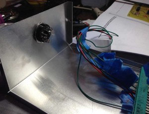
    New TTY Enclosure

    New TTY Enclosure

    New TTY Enclosure

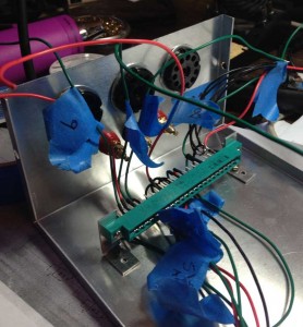
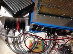
    After I clean the leaves off of the yard, I should be able to finish the TTY enclosure. I have been wiring the edge connectors first, labelling the wires with port and pin. After the edge connector is wired, I can put it in position, cut wires to final length and solder to the input and output ports. I think this works pretty well.

    With this enclosure, the port for the TTY device exits from the reverse end. Here is a view of bundle of wires that will be routed out that end of the enclosure.

    TTY Enclosure Reverse View

    TTY Enclosure Reverse View

    “Stonewall” Jackson’s Raincoat

    “Stonewall” Jackson was shot by his own men while in the front lines doing some scouting while wearing this rain coat.

    How come I don’t remember anyone, pointing out that from a short distance or in the haze, smoke and confusion of battle that “Stonewall” Jackson’s Raincoat would look almost identical to a Union Officer’s Frock coat. Seems like a poor choice of clothing for the occasion.

    I’m just saying…

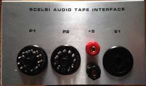
    Cassette Interface Enclosure

    Cassette Interface

    Cassette Interface Hooked Up

    I have my reproduction cassette boards mounted in the enclosure and functioning. I still have the adjustment and read LED holes to drill and lettering to do. I have rub on lettering ordered and should have it in about a week. If it works out well, I’ll provide ordering information from the vendor, and you will be able to order directly from them. I made use of some white space and added lettering for keyboard interface, power supply and oscilliscope interface to the sheet.

    A couple of hints on construction/assembly and wiring of the cassette chassis. The brackets are mounted about 2/3″ back from the end of the chassis. It’s a pretty tight fit in there. Mount the edge connectors on the brackets, but don’t connect the brackets to the chassis. Connect wires to the edge connectors. Then feed the wires through the holes in the panel and cut to length and solder to the connectors. Power and ground lines all go to the power and ground connections on the edge connectors. Power and ground of the two edge connectors are bussed together.

    The cable to the cassette tape recorder is only four wires. They are write, read, and two ground wires. Both ground wires connect to pin 11, read is pin 1 and write is pin 2. Tie-wrapped to the outside of this cable are the 2 wires for the motor on/off control. I think that SCELBI might have used the same 4 conductor cable that was normally used for connecting the power supply to the main chassis for this application.

    I’m still working on perfecting my silk screen making technique for the front panel. I’m determined to get to the point where I can get near professional quality results. Unfortunately I still have some learning to do.