Likely Changes to Cassette Board BOMs

I posted a preliminary copy of the cassette read and write board BOMs back in this posting.

Further investigation into the problem with the cassette write board reveals that the original SCELBI’s used revision A of the 7493 counter ICs, while I had purchased the original version. There seems to be significant differences in the specs, so I ordered a few 7493As to try. I’m fully expecting that the write board will work fine with the A revision parts, without having to change the capacitor. I have had very few problems with SCELBI designs in the past. I think that the inclusion of 7493As in production boards instead of plain vanilla 7493s was probably intentional, possibly to avoid the problem that I encountered.

The other change that is likely, is do to another image of the schematics that were sent to me. This version of the schematics have parts numbers labeled on the transistors. The image I received wasn’t all that clear, but the PNP types appear to be 2N2907 and the NPN types 2N2222. I doubt that the use of 2N3906 and 2N3904 on my reproduction in their place makes any difference, but I intend on updating the BOM.

SCELBI Cassette PCB Pricing

I just added two items to my SCELBI PCB price list.

A set of SCELBI cassette interface boards is $50.

A complete set of all 13 boards needed to make up a full, 12K SRAM, 4K PROM, SCELBI 8B, plus cassette and TTY interfaces is available for $475.

8B Front Panels are not ready yet, as I have been focussed on the cassette interface for the past several weeks.

Send an email with your address and and questions to:mike@willegal.net for a shipping quote and ordering information.

Using an Apple Powerbook as a Cassette Tape Recorder

During my debug of the SCELBI cassette tape interface, I decided I needed to get better visibility to the actual output of the cassette interface. There are a couple of ways to do this. One way was to use a DSO (digital storage oscilloscope) or logic analyzer to capture and analyze the signal. I don’t have either, so I had to resort to a second method. That is to capture the cassette output as an audio clip using an audio recorder and editor on a personal computer. One such application is Audacity, which is a free download.

The only trouble with using a modern personal computer is getting the audio clip into the PC. Apple Powerbooks include a headphone port that includes speaker out and microphone in. Wendell Sander has an Apple 1 site that includes directions on connecting an Apple 1 to an iPod’s headphone port. I did a bit of research and determined that the Powerbook headphone port is basically the same.

I constructed a dongle based on Wendells directions and hooked it up to an Apple IIe for testing. Unfortunately, I found that the Powerbook didn’t recognize the microphone input. After some more web searches I found a couple of sites that indicated that a 1600 ohm resistor between microphone in and ground would cause the microphone to be recognized. I hooked up a 1500 ohm resistor and found that it worked most of the time. The next larger size resistor in my stash was 2K ohms, so I switched to that and found that it worked reliably. I tested with the Apple IIe and found I could read and write reliably. I also decided to add a .1 uF capacitor on the microphone input line to decouple it.

I next switched to the SCELBI to capture the output of the SCELBI write card. This proved very helpful and with the help of the Audacity audio editor, I was able to zero in on the problem I was having. During the examination of the SCELBI cassette signal I noticed that the high frequency tone was greatly attenuated. This was due to the .33uF capacitor suggested in Wendell’s notes. The SCELBI uses much higher frequencies than the Apple. I needed to change the capacitor to .01uF so it didn’t attenuate the 2700 Hz high frequency signal used in the SCELBI cassette interface. The resulting circuit is depicted below.

powerbook cassette adapter circuit

powerbook cassette adapter circuit

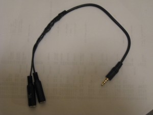
Here is a picture of the dongle. Note that I took a 4 conductor patch cord and cut it in two for the plug end. The reason is that the small clearances in 4 conductor plugs are difficult to solder cleanly. It was much easier to cut the wire and solder the wires and components together.

Powerbook Cassette Interface Dongle

Powerbook Cassette Interface Dongle

And here is a screen shot of the Audacity application showing a piece of SCELBI cassette audio out. The higher frequency portions represent ones, and the lower frequency are zeros. It takes 2 cycles of low frequency or 4 cycles of high frequency to represent a single bit. This encoding method is called frequency shift keying or FSK.

SCELBI Cassette Clip

SCELBI Cassette Clip

SCELBI Cassette Interface Now Working!

Yeah!! Finally a SCELBI 8B is working like it was meant to be with TTY and cassette interface. This may be the only working fully configured SCELBI 8B in the world at this moment.

After much investigation, which I’ll document more fully in later posts, I finally figured out the problem with the SCELBI cassette interface. Turns out that the problem was on the write board. The .02 uF capacitor on the inputs to Z14 (pins 3 and 4) was creating problems with the counter at Z4, which uses the same clock. Apparently due to the altered shape of the clock, the counter was not counting properly. This created chaos with the written data. I changed the capacitor to .004 uF and everything started working perfectly.

Once I made this change, I just slightly tweaked cassette player volume and I was able to write and read a small buffer of all zeros and another of all ones. I was also able to write a 2K buffer of random data and read it back without any parity errors. I need to do some more testing and tuning, but based on this initial experience, I’m expecting that this interface will work pretty well in practice.

I’ll need to take a breath and figure out board prices, which will be similar or less than the TTY board and then, at last, I’ll be able to start shipping cassette PCBs.

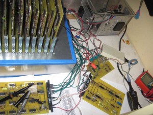
Here’s a picture of my current SCELBI 8B setup, with TTY card, Cassette read and write cards and RS-232 dongle all attached. The TTY and Cassette cards will eventually be moved to enclosures with female 78S11 Amphenol connectors. These will be connected with standard SCELBI 11(really 12) conductor cable with male 86CP11 Amphenol connectors on both ends to the chassis.

SCELBI loaded up with I/O

SCELBI loaded up with I/O

SCELBI Cassette Update

First, my previous post had a mistake. Input is low(zero) on high frequency and high(one) on low frequency. I forgot to account for the inverter that does the final TTL normalization.

The other good news is that I think I’ve been able to get a partial read of one of Mark Arnold’s recordings. It’s not surprising to me that I can’t get an entire read of a copy of a 40 year old recording. This is a move in the right direction, because it gives me a good look at how the read card recovers a proper SCELBI recording. In fact, the TTL normalized signal looks different than what I get from a recording coming out of my system. I need to look closer at my write card operation.

Cassette Read and Write Bringup Status

I’ve spent the last couple of days trying to get SCELBI cassette interface working. Though I have made tapes with the write card, I’m having trouble reading them back with the read card. I’ve also tried some original SCELBI audio files provided by Mark Arnold, but no go on those either.

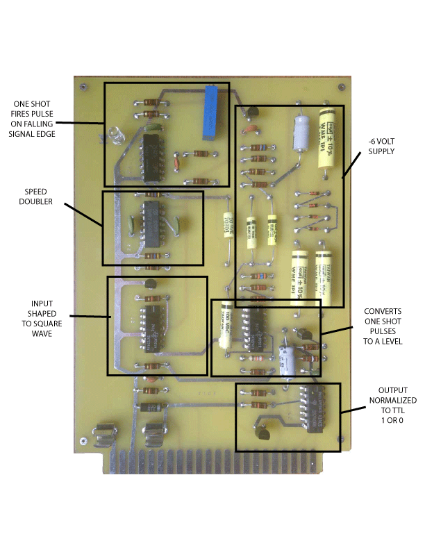
Assuming that my understanding is correct, the read circuit works much differently than what I expected to find. As expected, the first op-amp shapes and filters the signal into a nice normalized square wave. The following gates double the input signal speed and trigger a one shot on each falling edge of this double speed square wave.

Now here is the interesting part. The output of the one shot is filtered and converted into a level by another op-amp. High frequency signals will trigger the one shot more often tending to make the input to this op-amp to average a higher level than with lower frequency input. The output of the op-amp will follow the input. A TTL gate will normalize this output into a TTL one or zero, based on normal TTL level detection on the gate input.

I was expecting this circuit to work like a tone detector, where the circuit only triggers on a narrow range of frequencies. Instead the circuit divides the input frequency range into half and outputs zero on the lower half and a one on the upper half. The demarkation point is pretty much right between the 1350 HZ used for low frequency (zeros) and 2700 HZ used for high frequency (ones). The potentiometer can be used to tweak the center point to some degree. Experiments show that the output appears to be pretty unstable in the middle frequency zone.

There is also a -6 volt power supply built into this card that is used to power the op-amps, so that the card only requires a single +5 volt supply.

SCELBI Read Card Logic Blocks

SCELBI Read Card Logic Blocks

The read program works a bit like a serial interface, by starting sampling on what amounts to be a start bit at the beginning of a burst of four bits. By my calculations, the first bit is sampled after about 2.2 milli-seconds and then a software timing loop samples the incoming signal for the remaining 3 bits at about a 1.5 milli-seconds interval. Each four bit data nibble, is paired with a 4 bit parity and state/status nibble that is encoded the same way. Two such pairs make up a complete byte.

The problem that I’m seeing is that the parity check fails all the time. So far, I can’t find anything obviously wrong, either with read or write, but I have a lot more things to check out before I become “stuck”.

Apple II TTY Emulator Fixed

My previous posts described some barely working attempts at using an Apple IIe as a teletype replacement. When faced with bringing up my SCELBI cassette interface, I decided I needed to improve the Apple II based TTY emulation system.

After spending about a week of my spare time focussed on this effort, I think I succeeded pretty well. The hardware interface hasn’t changed from that previous post, but the TTY emulator now supports the standard SCELBI TTY software and hardware really nicely with full 72 columns and 24 lines. Most of that time was spent trying to overcome what appears to be a glitch in the hardware serial start bit detection.

Except for the initialization routine, I bypassed the Apple monitor character out functions and ended up writing my own output functions. Control characters behave like the SCELBI MEA application package expects them to behave. With the full screen now available, the new TTY emulation software is much more pleasant to use than the previous version.

I didn’t implement a cursor. Some people may feel this is a shortcoming. While a cursor would be pretty easy to implement, I decided that a real TTY didn’t have a cursor, so my emulator shouldn’t need one, either.

If you are interested, the source code can be found at this link:http://www.willegal.net/appleii/ttyemul-fs.asm

While working on this, I found one little issue with the MEA memory dump command. When dumping a full line of memory contents, it attempts to print a space character in column 73 of the TTY. I’d guess that a real TTY would just refuse to advance the carriage in this event. If you know how they really work, let me know.

I’ll need to port these changes over to my RTTY application, so it can also use a full screen. It’s not directly usable, because the RTTY runs at 45 baud and uses Baudot, instead of 110 baud ASCII. In any case, the RTTY port will have to wait, as next up on the to do list, is to check out the SCELBI cassette interface cards, which are built and waiting.

Captain Crunch’s Memory Modification

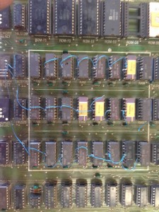
After I received the original snap shot of John Draper’s Apple II, I asked for and received better images. Here is one of them, showing the unusual Apple II memory arrangement.

Crunch's Memory

Crunch’s Memory

If you look closely, you will notice that all the memory banks are double stacked, largely with Signetics 2660 chips. These chips are 4Kx1, compatible with 4096s. This gives this system 24K of memory in 6 banks of 4K on each bank. Though I’ve seen double stacked memory on other systems, occassionally even on production boards, I’ve never seen this on any Apple II. Everyone else, managed to find 16Kx1 DRAMs and used those to expand their systems memmory. Don’t get me wrong, 16K memory chips were not cheap, especially in the early days of the Apple II. In fact for a long time, I ran my original Apple II with 2 banks of 16K and 1 bank of 4K for a total of 36K, which is all I could afford. I do believe John Draper’s approach is truly a unique solution to expanding memory for the Apple II.

What is more remarkable is this article, where John Draper, Capt. Crunch talks about his Apple II.

http://www.webcrunchers.com/crunch/Play/comp_rev/charlie.html

John mentions his Apple II memory configuration in the second paragraph, “My apple used the cheaper 4k rams and I piggy backed them to get 24k of ram.”

At some point, I plan on reviewing the wiring to see exactly how John wired up the 6 banks of memory.

I have more information on this system to post in later blog entries.

Apple IIe Fast Scroll Routine

I’ve been working on improving my Apple IIe TTY emulation application. One of the major limitations with it, is the amount of time it takes to scroll the Apple IIe’s screen, especially when in 80 column mode. In order to improve this function, I wrote my own fast scroll routine. Kind of interesting how close it turned out to a comment I received to a previous post, even though I forgot about that comment by the time I did this.

;
; Fast Screen Scroll Routine
;
LINE1 EQU $400
LINE2 EQU $480
LINE3 EQU $500
LINE4 EQU $580
LINE5 EQU $600
LINE6 EQU $680
LINE7 EQU $700
LINE8 EQU $780
LINE9 EQU $428
LINE10 EQU $4A8
LINE11 EQU $528
LINE12 EQU $5A8
LINE13 EQU $628
LINE14 EQU $6A8
LINE15 EQU $728
LINE16 EQU $7A8
LINE17 EQU $450
LINE18 EQU $4D0
LINE19 EQU $550
LINE20 EQU $5D0
LINE21 EQU $650
LINE22 EQU $6D0
LINE23 EQU $750
LINE24 EQU $7D0

FAST_SCROLL
  STA STORE80 ; enable aux mem
  STA PAGE2OF ; page 1 first
  JSR FS_DOIT
  STA PAGE2ON ; now do aux mem

FS_DOIT:
  LDX #39
FS_L1:
  LDA LINE2,X
  STA LINE1,X
  LDA LINE3,X
  STA LINE2,X
  LDA LINE4,X
  STA LINE3,X
  LDA LINE5,X
  STA LINE4,X
  LDA LINE6,X
  STA LINE5,X
  LDA LINE7,X
  STA LINE6,X
  LDA LINE8,X
  STA LINE7,X
  LDA LINE9,X
  STA LINE8,X
  LDA LINE10,X
  STA LINE9,X
  LDA LINE11,X
  STA LINE10,X
  LDA LINE12,X
  STA LINE11,X
  LDA LINE13,X
  STA LINE12,X
  DEX
  BPL FS_L1

  LDX #39
FS_L13:
  LDA LINE14,X
  STA LINE13,X
  LDA LINE15,X
  STA LINE14,X
  LDA LINE16,X
  STA LINE15,X
  LDA LINE17,X
  STA LINE16,X
  LDA LINE18,X
  STA LINE17,X
  LDA LINE19,X
  STA LINE18,X
  LDA LINE20,X
  STA LINE19,X
  LDA LINE21,X
  STA LINE20,X
  LDA LINE22,X
  STA LINE21,X
  LDA LINE23,X
  STA LINE22,X
  LDA LINE24,X
  STA LINE23,X
  LDA #$A0 ; clear last line
  STA LINE24,X
  DEX
  BPL FS_L13

  RTS

This routine takes about 18 milliseconds to run on a 1 MHz Apple IIe, compared to the standard monitor scroll routine which takes 34 milliseconds. Other than unrolling the loops, which would greatly expand the size of the function for a minimal speed increase, I think this is about as fast as it’s going to get.

18 milliseconds is still not fast enough for my TTY emulation package, so I’m going to have split it up into several segments and check for input events between segments. However, now that I have my own version of the scroll code, I’ll be able to split it up relatively easily.

There are some other issues with the standard monitor COUT routines for this TTY application, so it’s very possible that I’ll end up customizing all the COUT routines. For instance, I’ve already customized the “BELL” function for performance reasons. The Carriage Return function also had to be customized, because on a teletype, CR does not force a line feed.

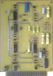
SCELBI Cassette Read Card Built

SCELBI Cassette Read Card

SCELBI Cassette Read Card

Since I didn’t have information on the transistors used, I choose vanilla 2N3904 (NPN) and 2N3906 (PNP) transistors for this build. The 72741 OP-AMPs are vanilla 741 OP-AMPs in a 14 pin package. They are pretty hard to find in that package, but I did manage to snag a few off of eBay. I described where I found the yellow capacitors in a previous post. You will notice one carbon film resistor in the mix. That is because I forgot to order a 2700 ohm composition resistor, and I happened to have the right value carbon film resistor in my stash.

This card is essentially just a tone detector. I should be able to test functionality and performance and adjust it without hooking it up to my SCELBI by using a computer based tone generator application that I bought a while back. This is what I did when resurrecting the HAL ST-6 TTY terminal unit. Except for frequencies used, it basically does the same thing, though at a much less sophisticated level.

One unique thing about this board is that there isn’t a single VIA present.