
What a awesome time. Here are some highlights.
Author Archives: Mike
CHM moves the PROM card in their SCELBI-8B into the correct slot
The CHM has the chassis of a SCELBI-8B on display in their micro-computer room. This chassis has 2 4K SRAM cards and 1 PROM card installed in 3 of the 4 memory slots. The PROM card has the standard EPROMs for MEA (monitor, editor, assembler) installed. For the longest time, that PROM card was in slot 8 of 9. This is incorrect, because of fixed addressing of the slots, MEA can only run out of slot 9.
Earlier this month, they moved the PROM card to the correct slot, slot 9. It was interesting from to hear from their curators about how carefully they documented this simple move for their archives. They told me, “We have a note in the permanent record for the SCELBI, including photographs.”
Reason for Lack of Posts this Month
I’ve been busy working on my VCF east exhibit.
It’s about the relationship between HAM radio and early personal computers. I have lots of interesting things to blog about. However I want to unveil my discoveries and experiments at VCF east, rather than reveal the exhibit contents ahead of time through blog posts.
Come to VCF east next month, and you’ll get the first look at what I’ve been busy working on. Sometime during or after VCF east, I plan on putting up some web pages and will have quite a backlog of stuff to blog about.
SCELBI 8H – boot up/debugging tips
I’m working on a 8008 amateur radio project for the VCF east. This project needs 2 input and 3 output ports, plus a serial input port for boot loading.
I have a working SCELBI 8B. The 8B has a memory editor in PROM, which makes entering a bootloader much easier than on an 8H. However, my SCELBI 8B is mounted on a temporary chassis that still only has a minimal number of I/O ports connected. When I build the final reproduction 8B chassis, I plan on connecting the full array of I/O ports. Until then, the port requirements for this VCF project dictate that I use my 8H for that application.
At this point, I have no PROM on the 8H. Downloading is through a 37 byte bit banged serial I/O driver that must be toggled in one byte at a time, using the front panel. It typically takes me about 30 minutes to initially toggle in the bootloader and boot the chassis with an application. What follows, are some tips that make booting the SCELBI 8H less troublesome.
I frequently make mistakes toggling in the bootloader. Troubleshooting a mistake can be difficult on the SCELBI. It used to take me quite a bit of time to correct these toggling errors. I have developed some approaches that make troubleshooting the bootloader fairly quick and very straight forward.
After toggling in the loader, I set the “L” register to a known location past the end of the boot loader, but in the same “H” page. This saves the time of having to toggle in a new value into the “H” register. I’ll connect the serial device that will be used to download the application, which is my case is usually a laptop computer. I start the terminal emulation program, and run the boot loader and enter a few characters using the keyboard. After typing in a few characters, I’ll interrupt the SCELBI and use the decrement L instruction (061) to back up the L pointer. Then I’ll use the load A from memory instruction (307) to read the contents of what I’ve written and verify that the character that I typed went into memory correctly. Entering a few characters with the keyboard before downloading the full application, allows you to skip changing the H register to point to the start of the application, while verifying correctness of the bootloader.
If the data doesn’t look right or isn’t making it to memory at all, I’ll toggle in the jump instruction (104 XXX XXX) to jump to the start of the bootloader. I can then single step through the bootloader to make sure I’ve toggled in the correct code. When you enter a loop, just verify one pass of the loop. After verifying by stepping through one pass, toggle in the jump (104 XXX XXX) instruction to go to the next part of the bootloader. This is much faster than stepping through the loop until it exits or reading back all of the program by reading memory indirectly with the HL registers and the front panel.
If I find a mistake, I’ll toggle in the load L immediate instruction (066 XXX) to point HL to that location. I’ll then use the load A from memory (307) to double check the contents of that location. If it is wrong, I use the load memory, immediate instruction (076 XXX) to correct it.
Next, reset L to somewhere other than the middle of your bootloader, run the bootloader and try typing in a few more characters. Once you are able to enter characters correctly, then point HL to the starting address of your program and download it. Be aware that if you forget to move the HL pointer, you may overwrite the some part of the bootloader. I have found that if you make this mistake, all is not lost. The SCELBI usually halts after destroying just a few locations of the bootloader, not the entire thing.
After sending the program down to the SCELBI, I do two checks. First, I check that the HL registers are one past the end of the program by loading A from memory (307) and monitoring the address read. If it is correct, I’ll decrement L (061) and load A from memory (307). The data read should match the last byte of the downloaded program.
Once the bootloader is in memory, try to avoid overwriting it. If your application doesn’t touch that part of memory and you don’t power off, it can be used to load a new application or a different version of the bootloader that can be located elsewhere in memory.
Familiar Sight
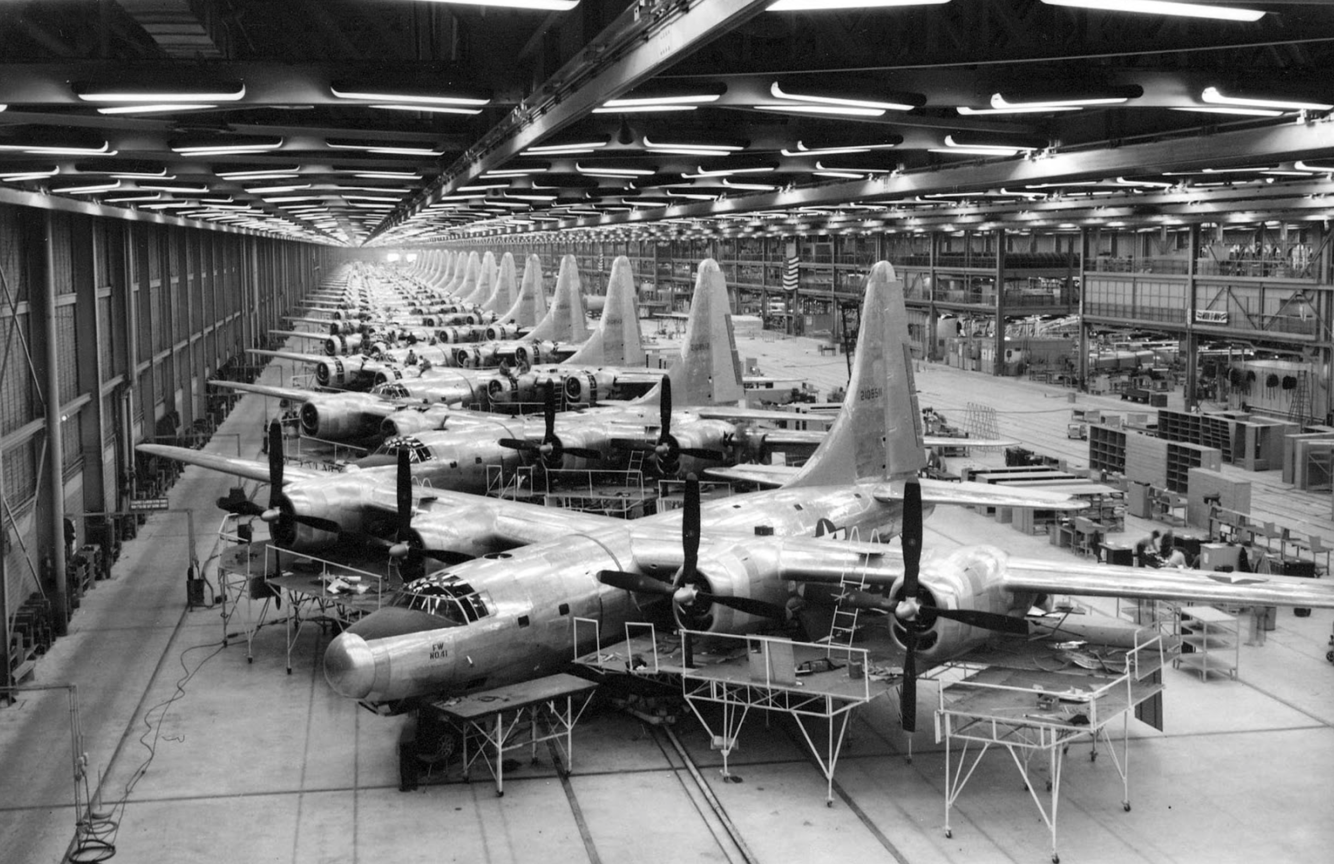
B-32 Bombers under construction at Air Force Plant #4
The photo was found on this blog page which contains much information about it: http://rarehistoricalphotos.com/b-32-bomber-factory-fort-worth-texas1944/
After looking at it, and reading the caption, I wondered if this was the same war plane factory that I had visited in the mid 80’s. At the time, I worked for the Computer Systems Division of Gould, Inc. This company produced super-mini computers and sold a large percentage of the computers used to power commercial and military flight simulators. When introducing a new version of the computer, some of the engineering team attended a show in Fort Worth, Texas. Before the show, a local sales representative invited us to visit the General Dynamics factory outside town. At the time, General Dynamics made F-16 fighter planes at the plant. We got to walk out on the factory floor. We could see workmen constructing F-16s, one rivet at a time. No automation or moving assembly line there, those planes were practically hand-crafted. Our guide told us that it was the longest factory in the world. He said that they rolled raw material in one end and complete airplanes out the other end. It was a very cool experience. Later on, at the show, I got to “fly” a General Dynamics F-16 cockpit proceedures trainer. What a memorable trip that was.
Follow this link to see F-16s under construction in this factory.
Well it turns out that this factory was indeed the same factory as produced 3000 B-24s during World War II and over a hundred B-32s towards the end of the war. It’s official name was Air Force Factory #4. There are a number of photos of this place while B-24s Liberators were being constructed on the Library of Congress website.
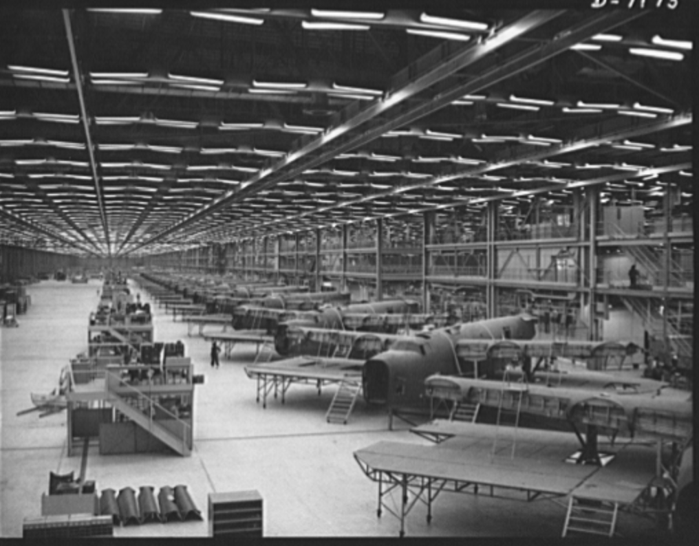
B-24s Under Construction
http://www.loc.gov/pictures/item/oem2002005697/PP/
Today the F-35 lighting II is produced at the facility.
A Side Project
One of the things that I have been hoping that I’d have time to do was to fully digitize the SCELBI manuals and add notes for the “modern” recreater. One of the main obstacles has been the extremely poor results from OCR software that I have used in the past. Well, I finally bit the bullet and spent some money on dedicated OCR software and am getting somewhat better results.
I’ve been working on the card assembly portion of the 8B build manual. So far, I haven’t added any modern reproduction notes, but have worked on getting the original manual transcribed. Here is what I have done so far.
Let me know what you think of this draft.
Infant Mortality?
If a 40 year old, NOS, IC dies after a few hours usage, should it be considered infant mortality?
glossory:
Corey,
Thanks for the inspiration for this post – too bad you were bitten.
Project Review – ME 1702/A Programmer
This is follow up to my previous post about building a Martin Eberhard 1702/A EPROM programmer.
In this post, I will share some more details about this project. This is not a kit, but Martin occasionally sells a PCB with a programmed PIC micro controller. Extensive instructions, including a parts list with recommend suppliers can be downloaded. Martin has sold several batches of these PCBs over the last couple of years, and I purchased a PCB and PIC from his most recent batch.
The programmer has a built in RS232 interface and can be controlled by any computer with terminal emulation software that supports capturing text to a file and sending text files. I use CoolTerm on a Macintosh for this functionality
All the parts have either Allied or Digikey parts numbers, so it is a pretty simple process of ordering your parts using Martin’s bill of materials. In my case, I found that I had some of the more vanilla parts already on hand, and I saved a few bucks by using what I already had. There are quite a number of different parts required. Usually when I order parts, I order spares of everything, but in this case, I ordered exact quantities of most parts, as I figured paying the postage for one or two damaged parts would be cheaper than ordering spares. In my initial order, I forgot to order one part and didn’t order enough quanity of a second part. These were my mistakes, as Martin’s bill of materials are right on.
I also made a couple of substitutions, one that didn’t work out so well. In the case of the DB-9, I purchased a male connecter instead of female. This is because most of my other devices with DB-9’s, use male connectors and this would allow me to use existing cables. In the case of the MAX232, I substituted a MAX202. The MAX202 has the same pinout as the MAX232, but uses .1uF capacitors. I had both the MAX202 and .1uF capacitors on hand, so this was a no brainer substitution.
The one that didn’t work out so perfectly, was the power supply plug, the Apple 1 uses the same form factor .156″ 6 pin header, so I used a connector from my stash of Apple 1 parts. Unfortunately the Apple 1 is a slightly different style, so the pins I bought, using the 1702/A BOM were not correct for the Apple 1 connector. I would have used Apple 1 pins, but I was out of them. I should have refered to my Apple 1 BOM in order to get the correct pins for my connectors. I was able to make do with the combination of connector and pins, but it’s not as secure as it should be. For now I have used silicon glue to secure the connecters to the housing. Next time I put in an order, I’ll get the correct connector and fix this issue.
I only have three colors of 18 gauge wire, so my color coding is not optimal. I used black for black, red for white and green for everything else. For the wires that go to multiple locations, I recommend running a pigtail and connecting multiple wires to the pigtail and covering the connection with heat shrink tubing.
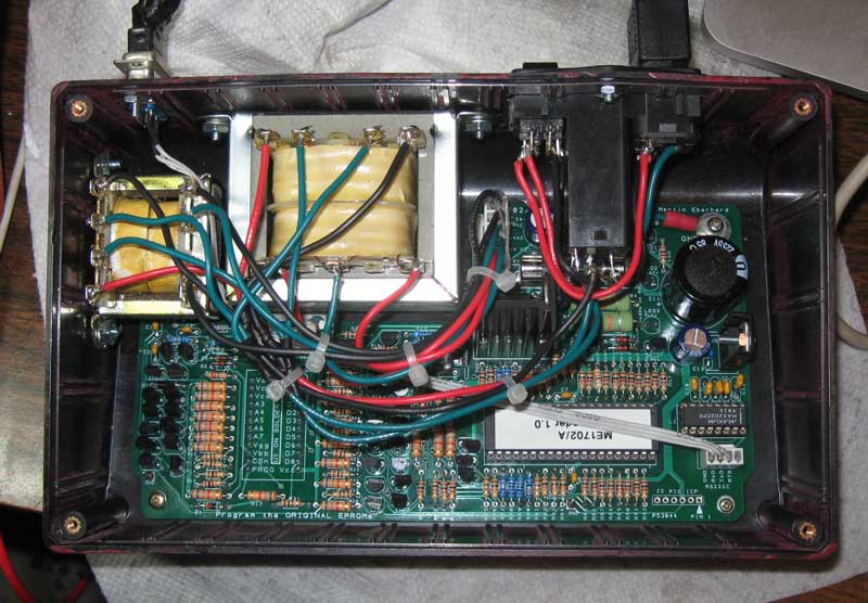
Inside ME 1702/a Programmer
Cutting the case openings was pretty time consuming. I made the cut outs by drilling holes in the corners of each cut out using the template from the manual. I then used a coping saw to connect each hole. This was followed by a lot of hand filing and tweaking with a dremel type tool with a cut off wheel attachment. The cut off wheel really helped me keep the straight edges, straight. Keeping edges straight would have been much more difficult with a regular grinding bit. For my first round of 1702 programming, I had borrowed a unit that had been painted MITS blue. That looked pretty nice, so I had to fill the sprue location in the front of my chassis and slap some paint on it. I’d guess that an expert could do it faster and better, and the paint job is pretty crusty, but I’m fairly happy with the result. I’m considering improving the paint job and making some decals or screen printing the chassis with a logo and lettering in the future.
One of the more time consuming parts of this project was wiring the transformers. Anyone that has done an Apple 1, will immediately recognize what is going on and be able to figure it out. During assembly, I made one mistake, and that was wiring the six pin .156″ power connector. That caused a blown fuse, but apparently no other damage. Make sure you know which end of that connector is pin 1 – the description is clear in the manual, but I guess I didn’t read it closely enough.
The instructions include rather detailed checkout instructions, and I recommend following them. My unit has two voltages that are a bit higher then specified in the manual. The first was found during Step 10, “Test High-Voltage Power Supply Control”. The voltage on the right side of R95 was just a shade over 75 volts. It is supposed be the combination of the drop over two zeners, 15 and 58 volts, which should have made the result about 73 volts. In my system, the drop over the 58 volt, 4758 volt zener, was just over 60 volts. This added to the 15 volt drop of the other zener resulted in the >75 volt reading. It could be that zener was out of spec, but I decided that it was probably close enough and moved on.
The other slightly high voltage was found in step 14, “Test High-Voltage Logic Signals”, where I found that logic low on the data signals was around .84 volts, when the manual said it should be under .7 volts. I looked at the schematics and measured voltages at several points in that circuit and couldn’t find any obvious issue. Looking at the 1702 spec, it looks like programming data low is -46 to -48 volts. Since the supply is 48 volts, that gives 2 volts of margin, so it should be fine. I decided to move ahead and try programming some actual devices.
I started with a part that probably had a burned out data bit. I did a number of experiments and could read the part and program each bit (except the bad one) and address successfully. Then I moved onto another part and proved out the bit I couldn’t test with the first part.
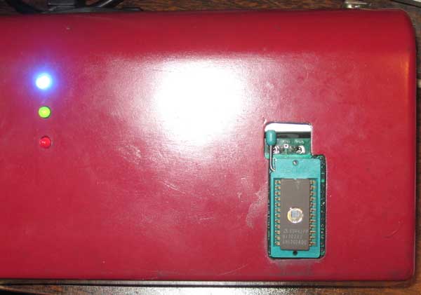
ME 1702/A Programmer
My Martin Eberhard 1702/A programmer appears to be working perfectly. I don’t have much mileage on this newly built 1702A programmer, but I can comment on the experience of using my friends, a few months back. At the time, I needed to program 16 devices for the SCELBI PROM board. I had very few issues during that session. I found two parts that didn’t blank check. Since I don’t yet have an erasing light, I don’t know if these parts are bad or just have been programmed before they got to me. I was able to program 16 parts that did blank check correctly with only one hiccup. That was one part that apparently hung the programmer, or was just taking a very long time to program. I power cycled and repeated the operation with the same part and it completed normally. I’m very impressed with this programmer, as well as the reliability of the 40 year old NOS 1702 EPROMs that I have had such good luck with.
Looking forward, I now have the capability to program the SCELBI keyboard and oscilloscope interfaces without having to borrow friends equipment. I expect I’ll have to go through several iterations of those drivers, since we haven’t found the original SCELBI software. I’m interested to find how these old devices will stand up to reprogramming.
I consider that building this programmer a medium sized project. Except for my own projects, I haven’t built any micro-controller based kits before. This one was really fun. I wouldn’t recommend it for a beginner, but someone who has been restoring or reproducing 70’s era computer systems for a while should have a lot of fun building this very useful device.
The cost will vary depending upon what you can find in your stash, but I think you should be able to build one of these units for $160-$180.
1702/A Programmer Project
I’m in process of building one of Martin Eberhard’s 1702/A programmers. I just finished soldering the PCB. and here is what it looks like.
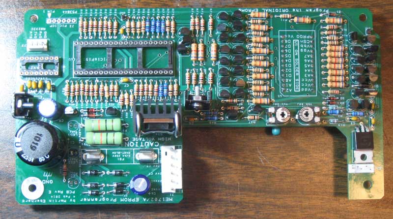
1702 Programmer PCB
The ZIF connector and three LEDs are mounted on the back side of this board, which will be mounted upside down in the enclosure. Martin did a great job with the layout – the overall structure of the layout reminds me of the Apple II’s layout, which, in my opinion, was a masterpiece in it’s day.
There are a lot of discrete components, but that is because of the high programming voltages required. At one point, I searched and couldn’t find any suitable integrated circuits that will handle the 50+ volts required to program this part.
I also have made the cutouts in the case and have painted it. The case is a plain black styrene plastic, so the paint really improves the look. Here it is, along with the two transformers and the power entry module. I have everything I need to finish it, except for the DB-9 serial port connector, which is still on order.
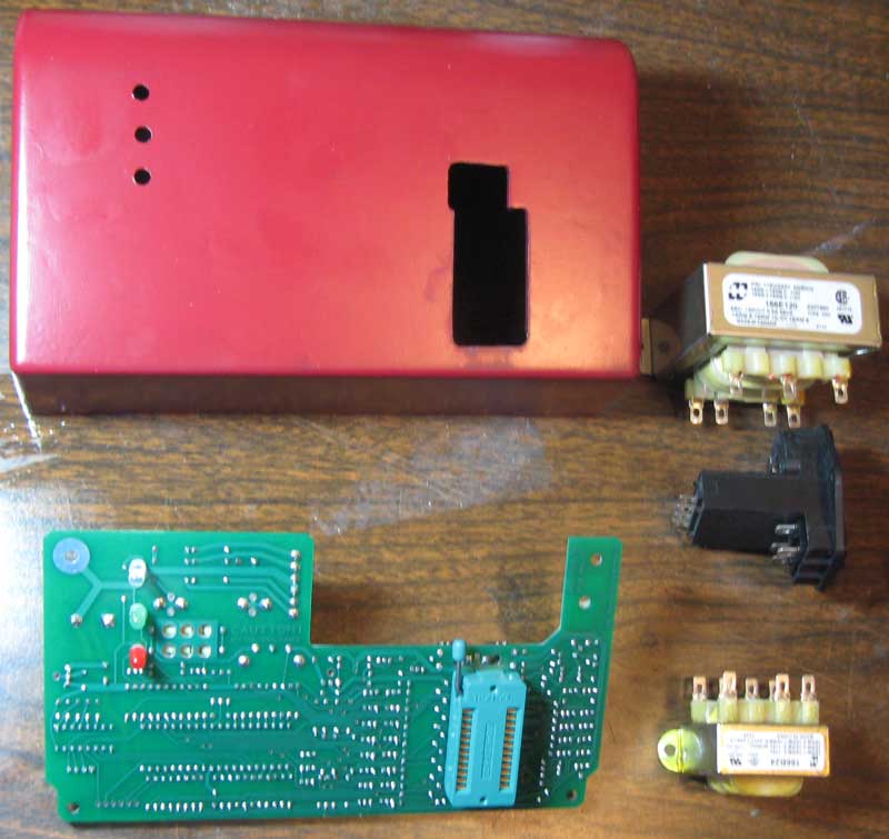
1702 Programmer – Major Components
I need to go back and check the detailed manual, but I think the next steps will be wiring the transformers and testing the power supplies.
SCELBI 8B panel logo update
In a previous post I commented that the Helvitica Bold was an exact match for the SCELBI-8B panel logo.
Well I went to digitize a recreation of the logo for eventual silk screening on a front panel and I found that I was mistaken. The panel characters are wider than the Lettraset letters and I couldn’t find a better match in the Lettraset catalog. Helvetica Bold was the closest that I could find, but as you can see, it’s too narrow.
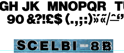
Helvetica bold overlaid on top of SCELBI-8B logo
These characters were scanned from the Lettraset book, scaled and placed over the top of the original lettering in Photoshop.
However, I was able to resolve the issue by stretching the scanned Lettraset letters horizontally, one at a time, in Photoshop.
Stretched Helvetica
I think the result is about as nice a match as you could hope to have.