Mind Blowing Update #2

less blur

less blur

After much delay mostly do to distractions with other projects, the software is done with no known open issues and the prototype board is working great. The production PCBs are order and will arrive in about 5 weeks. I thought I could get quick turn PCBs made, but this wasn’t to be, hence the long lead time. Here is timeline for future announcements and release.

1) I hope to have time to put together a video podcast showing a demo of prototype, so everyone can finally see what this is about. I hope to be able to post this sometime next weekend. I’ll also announce target pricing at that time.

2) The rest of the parts for the first production run will be ordered.

3) After taking a day or two to assemble and check one of the production boards for myself, I have two Beta testers lined up and they will get a few weeks to check out the board.

4) A web page will be created with downloadable instruction manual.

5) Assuming all goes well, I hope to be shipping in about 8 weeks.

Mind Blowing Apple Add On Update

This “Apple Add On” project is nearly complete. I have a prototype working, but need to tweak the software a bit. If I had pushed it. and put the Datanetics project aside, I could have completed it prior to Christmas. However, I have a bit of money tied up in the Datanetics PCBs and wanted to recoup at least some of it, before proceeding with another project that included a PCB build. That Datanetics PCB build is one project of mine that will never pay for itself, so don’t expect a rebuild in the future.

I have purchased a few of the more expensive components for the “Apple Add On”, along with some Datanetics parts that I needed. However, I’m not proceeding with the rest of component purchases or PCB build until the remaining 3 Datanetics PCBs are sold. If I can’t sell the remaining Datanetics PCBs via my my blog by the end of the month, I’ll go the eBay route. If you are thinking of waiting for the eBay sale, keep in mind that I will probably raise the price for the eBay sale, to account for added eBay costs. Selling these boards will free up enough “hobby” money to allow me to move on the “Mind Blowing Add On” PCB build.

radial blur

radial blur

I’m anxious to get moving on this, as I think it is a pretty nifty project that will sell for well under a hundred bucks and a lot of Apple enthusiasts will get a kick out of.

Adding Components to the Datanetics

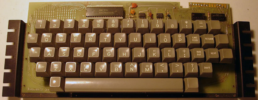
This morning I soldered the sockets, resistors, capacitors, and 555 timers (they are not mounted in sockets) onto the Datanetics PCB. There is a dot etched in copper near pin 1 of the DIP sockets. I used the schematics on my Datanetics page as a reference, so I put the seven resistors and three caps into the correct locations.

Components soldered in

While I had the soldering iron out, I also made two cuts on one of the shorted traces that makes an x towards the bottom of the front of the board and jumpered it over the other trace. This was a layout error on the original that I faithfully replicated.

cut and jumper


Before adding the MM5740 and 7404s, I wanted to check to see if the 555 timers were generating good clocks. in order to do this I needed power. Rather than mess with jumpers, I figured I might as well as wire the DIP – ribbon cable – Edge connector. This picture was taken later on, but shows how it is wired. The red aligator clip is a ground probe connected to my oscilloscope. Once I confirm that everything is working, I’ll apply some heat to the heat shrink tubing to lock it in place.

Edge connector

Connections from the A1 keyboard DIP socket to the edge connector are as follows.

EDGE CONNECTOR TOP (12 positions connected)
starting on left side
-12V – CONNECTOR PIN 1 to DIP PIN 11
B6 – CONNECTOR PIN 2 to DIP PIN 7
B5 – CONNECTOR PIN 3 to DIP PIN 6
B4 – CONNECTOR PIN 4 to DIP PIN 2
B1 – CONNECTOR PIN 5 to DIP PIN 5
B2 – CONNECTOR PIN 6 to DIP PIN 4
B3 – CONNECTOR PIN 7 to DIP PIN 3
RST1 (RST) – CONNECTOR PIN 8 to DIP PIN 1
RST2 (RST-GND) – CONNECTOR PIN 9 to CONNECTOR PIN 15 (GND)
STROBE – CONNECTOR PIN 11 to DIP PIN 14
B7 – CONNECTOR PIN 12 to DIP PIN 8
GND – CONNECTOR PIN 15 to CONNECTOR PIN 9 to DIP PIN 9

EDGE CONNECTOR BOTTOM (3 positions connected)
Counting from same side as we started with on top
+5V – CONNECTOR BACK PIN 4 to CONNECTOR BACK PIN 9 to DIP PIN 15 to DIP PIN 16
CLEAR SCREEN – CONNECTOR BACK PIN 8 to DIP PIN 12
CLEAR SCREEN (+5V) – CONNECTOR BACK PIN 9 to CONNECTOR BACK PIN 4 (+5V)

Next I connected the keyboard to a Mimeo and powered up in order to check the clocks. Like always during a first power up, I first checked for hot chips and for good voltages on the power supply. Then I checked repeat and MM5740 clock with an oscilloscope. Everything looked just fine. By shorting the pads together at the location of the reset key, I was able to verify that reset was connected correctly. By doing the same, I was also able to verify that clear screen worked. Next step was to plug in the chips and see if I could enter characters.

Testing the Datanetics

Testing the Datanetics

Finally I plugged in the MM5740 and the two 7404s and powered up again and checked for hot chips. After clearing screen and reseting, I went through the keyboard shorting each pair of pads making sure that each key worked. Then I jumpered the shift key and checked that shift characters worked. I also tested the repeat function. So far everything is working fine. The next step is to add the key switches.

test jumper in shift key location

Datanetics Brackets Mounted

I finally recieved all the parts I need to complete assembling and testing of the reproduction Datantics PCB.

I carefully drilled 1/16″ holes to match each bracket to a couple of mounting holes in the PCB. Then I inserted the eyelets and used the eyelet setting tool to set them and secure the bracket. I then drilled the rest of the holes, and set the rest of the eyelets.

brackets attached

You have to careful with this work. Two eyelet sizes are needed, keystone #26 where you only have one bracket to go through. #27 in the four holes where both brackets overlap. I used an inexpensive eyelet setting tool that I got from volcano arts. After completing this task, I would say that the holes in the PCB are slightly bigger than optimal for the 1/16″ eyelets. Despite this, the eyelets worked out fine in my board. Have I mentioned that one of the biggest problems I have with these reproduction boards is getting the hole dimensions right. This is especially hard when I don’t have engineering drawings for the original parts.

more pictures of the brackets

bracket attached

bracket attached

back of board

Back of Board with Brackets Attached

Back of Board with Brackets Attached

The blue edge connector seen in these photos will be wired to a ribbon cable for connection to my Mimeo motherboard. It is Digikey part number S3345-ND. The key thing with these edge connectors is the spacing which should be .156. There are 15 positions per side for a total of 30 contacts. I got the edge connector dimensions right, the connector fits perfectly.

Solder Sucker Woes and Stuck Screws

Pulling the Datanetics keyswitches from an old keyboard takes time and skill. You have to suck the solder from the holes/pins, before unscrewing the switch or you could pull the switch apart or the pin out of the switch.

After pulling about 40 switches, I noticed that my spring operated solder sucker wasn’t sucking much solder anymore. I should have noticed sooner, as the solder was getting harder and harder to get out, until finally the solder sucker refused to operate at all. At that point, I knew it wasn’t working right. I took it all apart, got as much solder out of the tube, as I could and even oiled the tube with a plastic compatible oil. I reassembled and operation returned to as good as new, maybe better. The improvement was so vast, that the last 10 switches took as long to get out, as the previous 2. Moral of the story, proper maintenance of your solder sucker will prevent vast amount of frustration.

Also, the screws holding many of the switches onto the PCB were extremely hard to get out. I had to file the head on an 00 phillips screw driver to exactly fit the profile of the screws or I wouldn’t have been able to get some of them out, at all. I’m not sure what the moral is here, other than phillips heads screws suck.

Keyboard Update

Keyswitches – though I have a batch of NOS (new-old stock) Datanetics key switches with straight stems, the original Datanetics had slanted stems. I decided that using straight stems on such an otherwise faithful reproduction would not be proper, so I’m doing a transplant from an older II plus keyboard that has the correct slanted stems. The NOS straight stems will go into the II plus keyboard. That II plus keyboard has seem better days, but is a fairly early one, so deserves to be restored. I’m waiting to attach the brackets and siffener to the Datanetics, before soldering the keyswitches into the Datanetics keyboard. There are more switches on the Datanetics than on an Apple II plus, but I have a few extra switches from a previous project that can be used to make up the difference.

Brackets/stiffeners – I have bought a new 1/16″ drill bit in which to drill the rivet holes in these parts. I have rivets on order and will wait for the rivets to arrive before drilling. That way I can drill the first one or two holes, attach those rivets and be sure that registration of the rest of the holes will be good. I think Keystone #26 and #27 eyelets should do the job. This place has what looks like #26 eyelets, plus an eyelet setting tool. Mouser has both #26 and #27 eyelets.

http://volcanoarts.com/cart/eyelets/index.htm#1/16Tool

I’ll have to figure out final keycap solution at some point. For now I’ll manage with an Apple II plus set. Several folks are talking about getting a custom set made – so there may a group buy in the future.

There are two possible routes to go in regards to the connector. One solution is a PCB style board edge connector mounted onto a small PCB that will accept a 16 pin DIP header. The other is wiring the ribbon cable from the Apple -1 directly to a board edge connector. The row spacing is .156 and it has 15 positions/30 contacts. It seems like both Digikey and Mouser have stock of both PCB mount connectors and the ones with eyelets for direct wiring.

I drilled out the vias in the matrix on my PCB yesterday with a #67 bit and a pin vise. My bit wasn’t particularly sharp, but it worked out fine. I could have used a drill press, but using the pin vice ensured that I would go slow and helped avoid any mistake. I used an ohm meter to verify that the connections were broken and only had to go over a couple of holes a second time, to break the circuit. When doing this, you have to be careful that you only drill out the vias in the matrix area. There are some nearby vias that need to be left intact.

I also used a pin vise and a 1/16″ bit to ream out the slightly undersize mounting holes for the keyswitches. These are still a tight fit, so some more reaming may be necessary when I finally mount the keyswitches.

Datanetics PCB here

I’m really pleased with the result and think every Apple 1 owner will want one!

reproduction datanetics keyboard

compare the replica to the real thing which can be seen here http://www.willegal.net/appleii/images/dataneticsrevb.jpg

Many thanks to Mike Gregory for doing an excellent job cutting/bending and painting the brackets.

Besides finding your own components, it’s going to take some extra skills in order to put this together, including some drilling of brackets, mounting of eyelets, drilling out of vias and reaming of the keyswitch mounting holes (some were made just a bit too small). No detailed instructions will be provided, either. I’m calling this a level 5 kit (the hardest) in my new kit skill level grading system. Grades of other kits are as follows.

1) Apple Cassette Interface
2) PS/2 keyboard adapter
3)
4) Apple 1, Apple 2
5) Datanetics keyboard

Only 10 are have been made and most are already accounted for. Send me an email if you want more information and to get on the interest list.

Datanetics PCB update

I’ve had a pretty small response to the offer on the Datanetics PCB.  Despite the small numbers of folks interested, I’m still going ahead with this as a one time deal.  Before doing so, I’m going to spend the next couple of days looking for better pricing on the PCB.  Ordinarily I’d stick with my current fab house, since since I have had such good luck with them.  However this PCB doesn’t have a solder mask or silkscreen, so I should be able to find a cheaper place to do this board and still get good results.   Since I haven’t collected money yet – if I turn up a better price, I’ll adjust the pricing.

Datanetics Keyboard Plans

These PCB boards are turning out to be very expensive to make, partly because of the need for the array of unplated vias in the encoding matrix on the upper left side of the board.  These unplated holes push this project into a custom fab process pricing, which increases cost by 25%.  Because of this, and the specialty nature of this project,  I’m not sure how many to order.  What I’ve decided to do, is to make November a pre-order month.  At the end of November, I will order enough to fill the pre-orders only.  There are no plans to stock or inventory any of these PCBs to sell later on.  The cost of the PCB will be $79 and will include no hardware, chips or other components.  I can’t even guarantee the PCB will be error free.  Actually I’m reproducing a design error that was on the original, but beyond that I can only say that I’ll do the best that I can.  However, if they turn out to be unusable, I’ll eat the cost and either get a new batch made or refund your money.  Shipping within the lower 48 US states will be free. Add $25 for overseas shipping.

Pre-orders will the accepted through the end of November.  Fabrication of the PCBs is expected to take a month, and shipment to you about a week after that.  Which would put the PCB in your hands in the first half of Janurary.

send email to “mike@willegal.net” for preordering information.

PS. If one of us can find a sheet metal vendor to do the stiffeners, I’ll be glad to coordinate a batch purchase of those at cost.