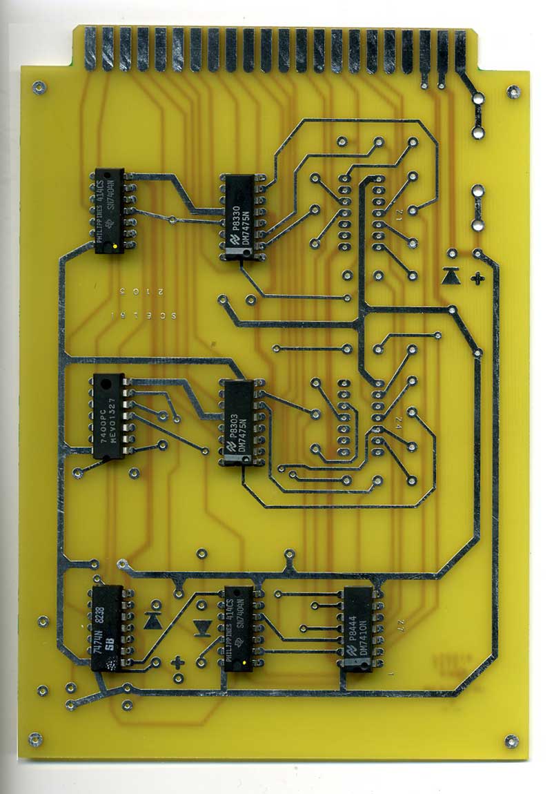
Over the weekend, I started work on the SCELBI O’Scope PCB layout. There are two boards that make up the package, a standard size analog board, and a double width digital board. The standard size analog board looks like it will be pretty easy to layout. However the double width digital board looks pretty complicated. It has 35 chips, and around 220 VIAs. By comparison, the Apple II, rev 0, which has to be the most complex PCB that I have recreated has about 380 VIAs. The chip count is the second most for any SCELBI board. It trails behind the 4K SRAM board, which has 37, 32 of which are SRAM chips. All the SRAM chips on a SRAM board are connected the same way, which simplified things quite a bit on that board.
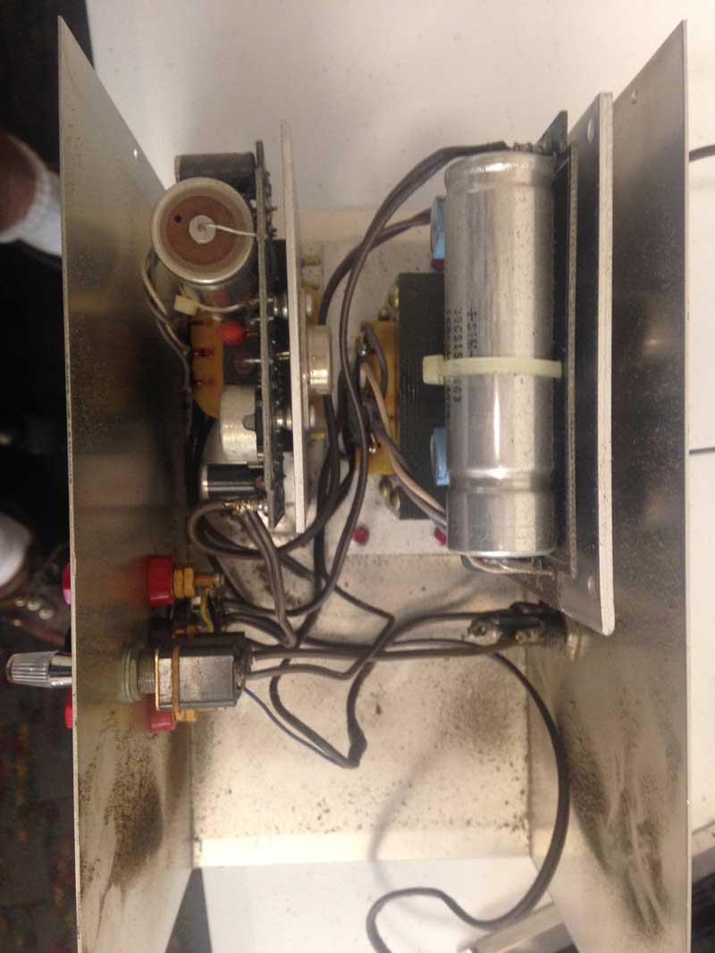
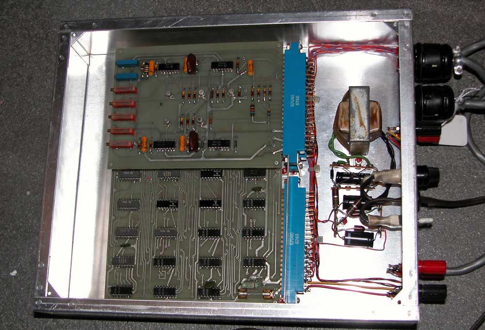
Image of the Inside of the O’Scope Interface at the Computer History Museum (courtesy Jack Rubin)
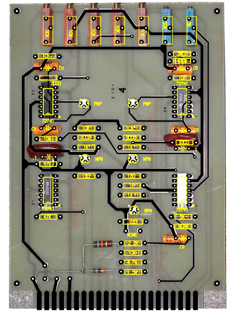
The good news is that, so far, I haven’t run across any components that will be excessively difficult to find.
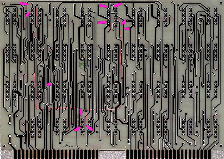
Another complication on the digital board, is that I only have three good images of two different O’Scope boards. The front and back of one board, and the front view of a second. The board that I have front and back views of, has quite a bit of rework on it. I don’t know if these are design issues or customer modifications. It will be interesting to sort through these changes and see if there are any differences between these two boards.
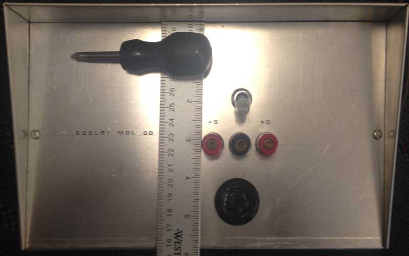
The final challenge will be figuring out the details of the power supply that is integrated into the O’Scope chassis. At this point, all that I have to go on, is a picture. When you put everything together, the SCELBI O’Scope interface turns out to be far more complicated than many single board “trainer” type computers.
The keyboard interface layout is complete. I have done design checks and have a quote in hand. I probably will not order boards until the O’Scope layouts come together, or at least until they get further along. I think of the keyboard and O’Scope boards as kind of a matched set, the keyboard for input, and the O’Scope for display output. One, without the other is kind of a half solution, though I will be able to test them out independantly.