Beta sales of SCELBI boards sets is open from now through February 1st. The special beta/introductory price for a board set during this beta period is $225.
The board set includes:
1 Front Panel PCB
1 CPU PCB
1 DBB PCB
1 INPUT PCB
1 SRAM PCB
1 Backplane PCB
You can optionally add an untested 8008D microprocessor for an extra $25.
Shipping within lower 48 US states is free – shipping elsewhere is $35. Shipment will occur around February 2nd.
Notes:
Only 1 SRAM board allowed per set in this initial sale. Once system operation is confirmed and I get an idea of amount of interest, I’ll get another batch of SRAM boards made and will offer them for sale.
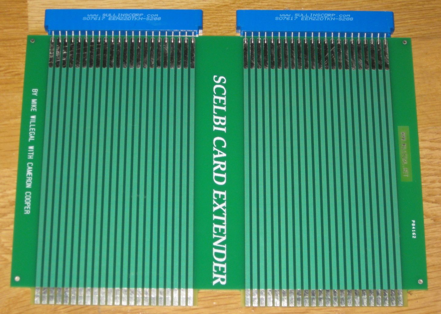
Like the original SCELBI, all boards are two sided with plated holes and a 2 OZ copper layer. There is no solder mask or silk screen.
Chassis mounting holes for the backplane PCB were purposely left off, in order for the builder to precisely drill holes to match holes in the builders particular chassis.
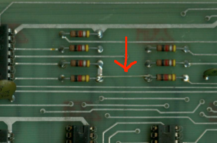
At this time, I only know of one minor issue with the board set. That is that the holes for the over voltage protection zerner diodes were not made big enough for some higher wattage zerner diodes that have thicker leads. The easy fix for this, is to drill out the holes and, where necessary, solder from both sides of the PCB to ensure connectivity between front and back sides.
During this special pricing period, PCBs and the 8008 should be considered untested prototypes that might possibly require some rework to be made to work correctly.
Find more about the SCELBI, bill of materials, reference information, progress in bringing it to life, by following my 8008 blog category at http://www.willegal.net/blog/?cat=16
Please send an email to mike@willegal.net for payment information.