SCELBI APP with Oscilloscope Display Interface
I haven’t been getting very far in improving the SCELBI Oscilloscope software drivers. I think I was blocked, because I prefer not to spend time debugging software with actual vintage hardware. Emulators are so much easier to work with. Finally I bit the bullet and started work on adding Oscilloscope Interface emulator to my 8008 emulator.
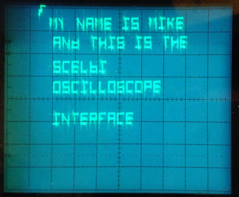
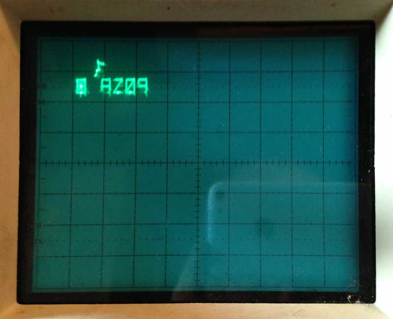
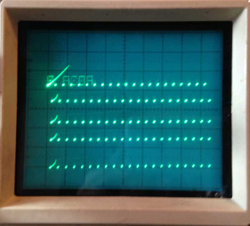
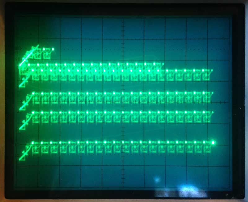
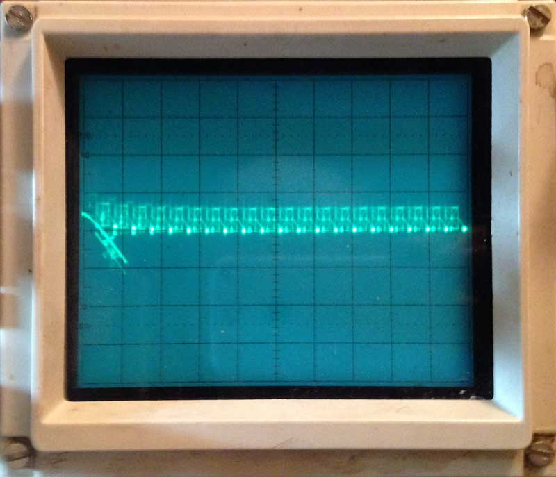
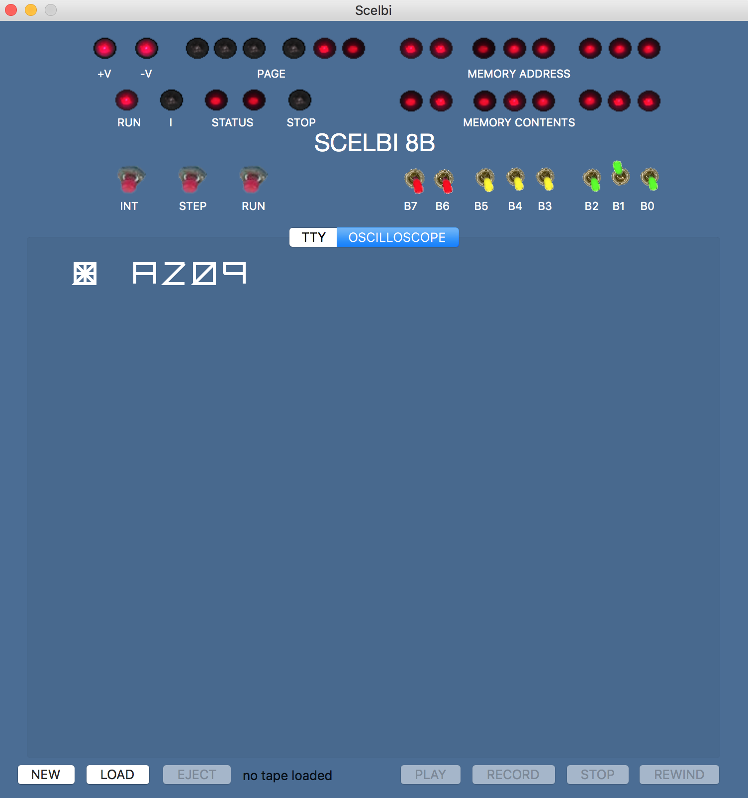
I spent a marathon session working on this over the last day and half. This is a work in progress, but at least the 8008 driver I used to initially check out the real thing displays a few characters.
The interesting thing is that the part I feared the most, using the OS/X toolbox to draw the characters, actually has been the easiest part of this effort. OS/X embeds vector graphics primatives into the operating system, so drawing characters with vectors turned out to be pretty simple. Interfacing to the 8008 I/O instruction emulator also has proved to be pretty straight forward. Adding a tab to switch between TTY and Oscilloscope windows, was almost trivial.
I need to emulate the dynamic nature of the oscilloscope interface in order to make the emulator work right. Updating, erasing and changing the display is taking a lot of effort. Keep in mind that with the oscilloscope display, if the 8008 stops driving the output, the display disappears. The operation of the real thing is pretty dynamic, which isn’t something that computer displays do very naturally. There is some kind of animation support built into the OS/X toolbox, but I’m not sure I’m up for finding out if that will make my life easier.
Once I got started on this, I have been thinking about emulating scope controls, as well. By the time I’m done, I’ll might add some simple horizontal and vertical scaling controls, and perhaps some positioning controls. How much I do, if anything, remains to be seen.