SCELBI Oscilloscope Analog Board
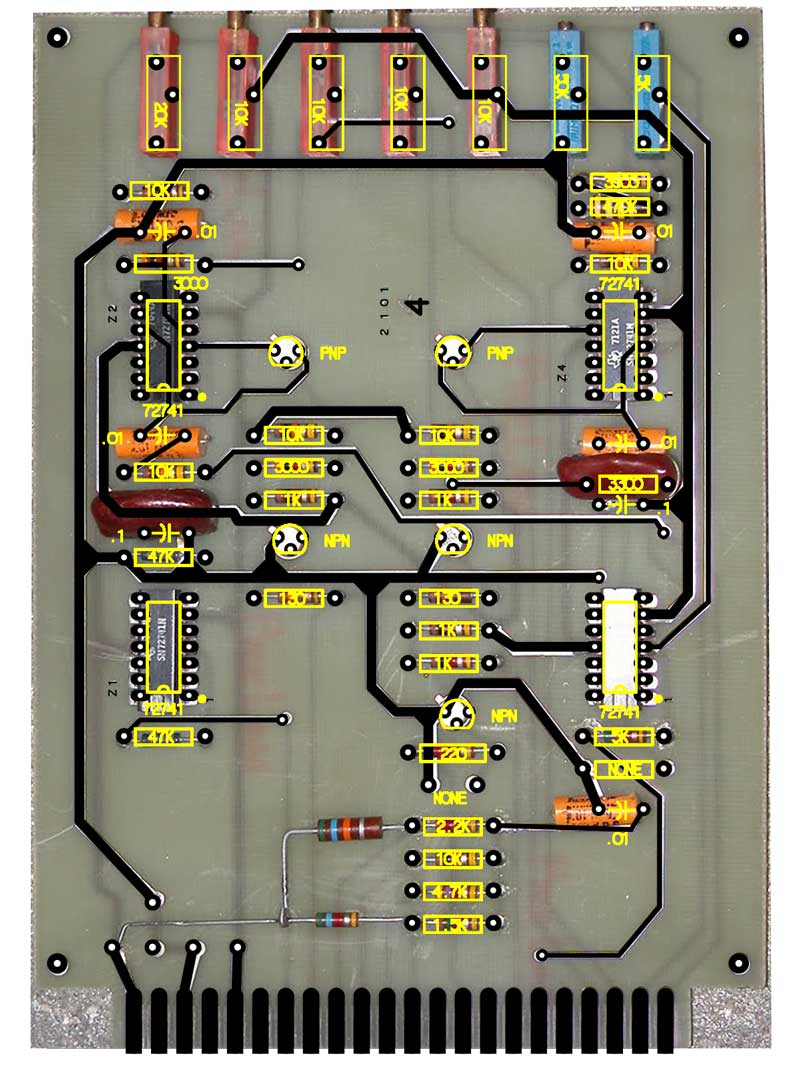
Here is an image of a SCELBI analog board. Overlaid on top is my current front copper layout and a silk screen layer showing component mix. As you can see, the layout is very far along, considering that I’ve only worked on it for parts of two weekends. There is still plenty of tweaking and checking to be done, but there is good chance that the layout, as it stands, would work.
Note that this board has several component locations without components stuffed and a couple of 56K resistors tacked on. There are no pads for these resistors, but they show up in the schematics and on the SCELBI placement diagram. I wonder if there was a second batch of cards made with corrections?
The 130 ohm resistors are listed as 100 ohms in the schematic. It would be hard to know why there was a difference without doing some experiments on actual hardware or a circuit analysis. This change could be functional in nature or do to using components that were close enough and on hand. The 3K resistors are listed as 3.3K in the schematics, but I think they used what was on hand, and there probably isn’t a functional difference in that case.
The pads in the lower left are for decoupling capacitors. I don’t know why they weren’t stuffed in this example. The component mix is pretty basic. There appear to be some film and mica capacitors. Based on what I’ve seen on other SCELBI boards, the transistors are probably 2n2222 and 2n2907 types, but I don’t have confirmation on that. Probably the most expensive parts to source are those pesky 72741 op-amps in 14 pin packages. They seem to be available on eBay, but the asking price is very high. I’m going to be on the lookout for a better source.
One final thing that threw me for a loop on this board. When compared to all other SCELBI boards, the DIP packages are mounted upside down. I’m going to have to pay attention when assembling this board.