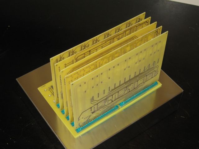
Prototype Chassis with backplane installed – top view
SCELBI chassis-top view
This is the result of some hacking of a backplane into a BUD AC413 chassis. The AC413 is the same width (12″) and depth (10″) as an original SCELBI chassis. However the BUD AC413 is 3 inches tall, while the original SCELBI chassis 3.5″ tall. During this prototyping/hacking effort, I found out a few important things.
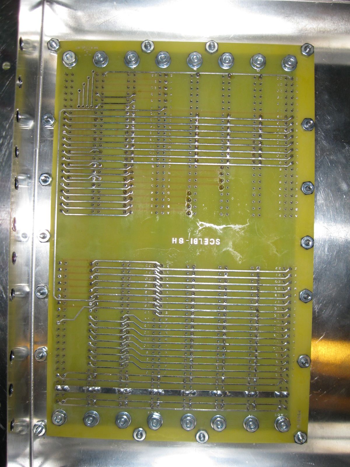
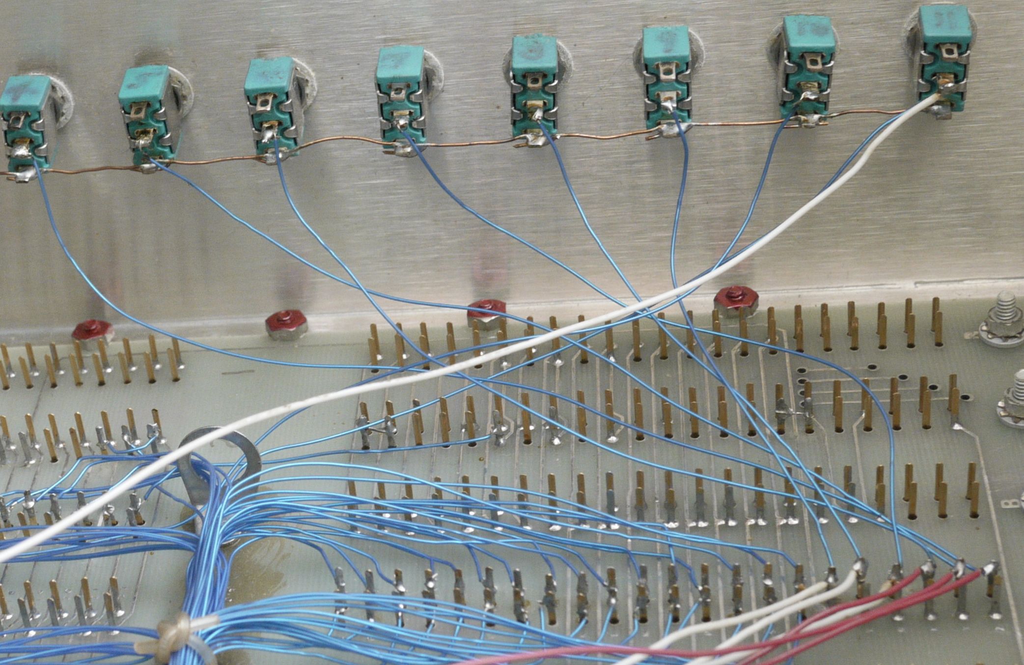
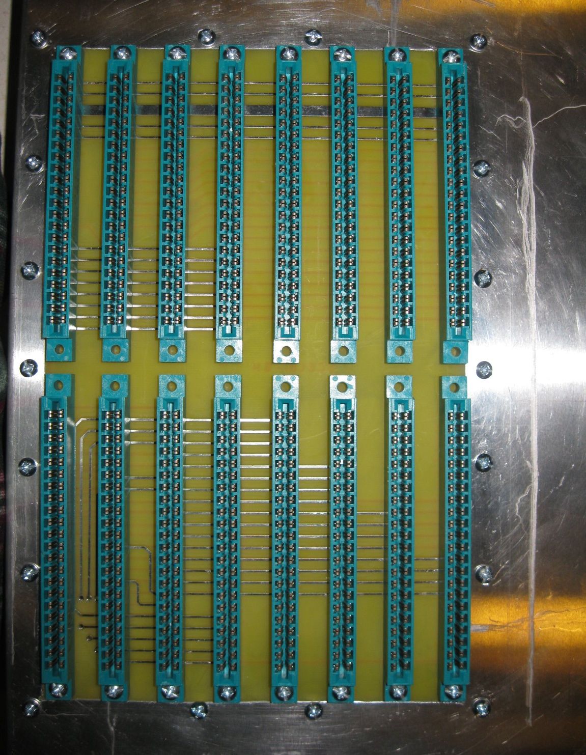
SCELBI Chassis Bottom View
A view from the bottom.
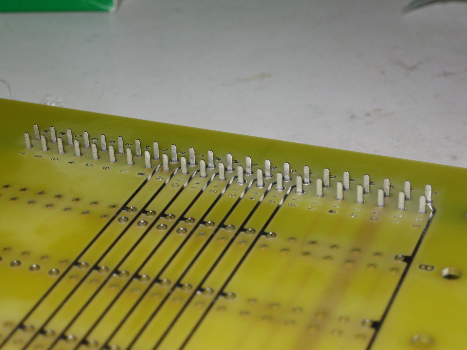
When soldering the edge connectors, only the pins with connections and pads are soldered.
One more thing – I positioned one of the holes for the edge connector mounting screws 1/16″ too far back. This hole will need to be drilled out to properly fit a #6 screw. However the error is so small that the enlarged hole cannot be seen under the nut of the screw or the ear of the connector.
An insulated stiffener running down the center of the board between the connectors would have been a good addition to this design.