
No work today due to MLK holiday, I’m like a kid waiting for Santa…will send update to blog with early assessment and details on early adopter program later on…
Monthly Archives: January 2013
SCELBI: things to be aware of SCELBI
As I layed out the PCBs and researched things SCELBI, I discovered several things that other SCELBI builders should be aware of. I fully expect that other things will crop up, like they did during my Apple 1 and Apple II builds, but here are a few things that I know about already.
+5 volt wire on DBB board
anyone know about using Molex pins to make a IC socket?
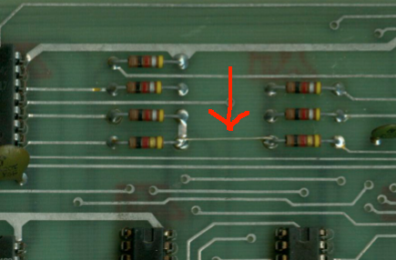
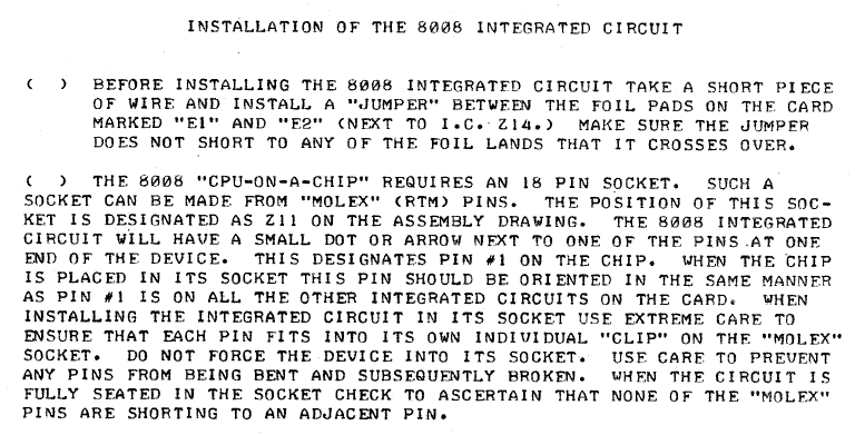
From the SCELBI CPU assembly manual….
Molex pins to make socket?
Anyone heard of this technique?
Please send an email to mike@willegal.net with a description of the exact molex parts to use, if you have.
Sellam’s Great Loss
Through a tragic series of event’s, Sellam Ismail has lost the part of his vintage computer collection that was in a storage facility. Apparently Sellam was unable to pay his rent or remove his property from this facility. After some months, the proprietor took possession of the goods and has contracted with someone who is selling it off on ebay.
Though I haven’t met or spoken with him, by all accounts, Sellam is a nice person, and certainly an asset to the vintage computer community. It is unfortunate that he didn’t find a way to relocate the collection or pay his bills on time. I wonder if he had taken the simple expedient of selling off a few valuable items when money got tight, he might have been able to maintain the bulk of his collection. Certainly this isn’t unprecedented, as the Huston brothers decided to part with some of their valued items, when money became tight for them.
The breakup of this collection should be taken as a warning to those people in our community who pursue collecting at unreasonable financial risk. I often receive email from folks who would love to have a Mimeo, but can’t afford it, or from people that don’t have much experience with vintage computers and want to start out with a Mimeo. I frequently advise people in this category that there are many ways to enjoy vintage computers, without spending a lot of money and incurring a lot of financial risk.
I generally don’t like to editorialize on my website or blog, but in this case, I think a little word of warning to those that might spend beyond their means is appropriate.
SCELBI Update
Boards are expected to arrive next Monday. I’m still weighing details of the early adopters plan, but I’m leaning along these lines.
Assuming that board pass the eye test and some basic mechanical checks, I’ll probably accept payment for a shipment on the next Saturday or Monday after board arrival for those that want the best price, and are willing to risk untested HW.
Then I’ll ship a second wave after two more weeks, still with reduced pricing, but not rock bottom pricing.
After that, I’ll go to a standard price that I can live with going forward.
Just to give you an idea of pricing range I’m thinking about is in the range of $200 to $300 for a six board set, with no components.
SCELBI computer sold kits, as well as build up computers. Be aware that building a chassis for the SCELBI 8H can get surprisingly expensive, depending upon how close to a production system that you want to make it. For a bare bones setup kit type setup, you’ll need 10, 44 pin edge card connectors, and +5v and -9v power supplies, plus some switches and a chassis of some sort. You will need wire to connect the power supply and front panel switches.
For a more authentic “production” system, SCELBI used 14, 78S11 relay sockets for I/O and a total of 16 edge card slots. Also, each slot had card guides in production systems. The power socket is a 78S4 and the plug is a 86CP4.
The chassis is similar to a BUD AC-413, only 3.5″ high, instead of 3″. Cory is looking into the cost of getting a custom chassis made that is a close reproduction of the SCELBI original, along with an anodized blue front panel.
I’ve ordered a set of edge card connectors – once I confirm that they will work, I’ll post the part number. Also, I believe I have identified the correct card guide, but need to confirm that before I publish the number.
I think that all existing SCELBI 8H documentation, including assembly manuals and schematics can be found online at one of the following sites.
http://www.scelbi.com
http://bitsavers.trailing-edge.com/pdf/scelbi/
http://www.olson-ndt.com/Scelbi/
regards,
Mike W.
More on Apple 1 -5 Volt Supply Issues and a Solution
My friend Lionel, from Australia, reports to me about an issue with DS0026 clock driver chip on his Mimeo build. The Apple 1 was originally designed with a DS0025 clock driver chip, but the DS0026 should be a compatible replacement. The DS0025 drive a pair of clocks that are used for shifting video data through the 2504 shift registers. This clock low level is -12 volts and is the same clock that is coupled to video output and causing the video dot problem described on my Apple 1 Hardware Notes page.
After doing some investigation, Lionel and I have determined that the 2504s are coupling this clock
http://www.willegal.net/blog/?p=1623 onto the -5 volt supply. This is what is causing a large part of the noise on -5 volts and manifests itself as intermittent DRAM problems (failure to pass memory tests).
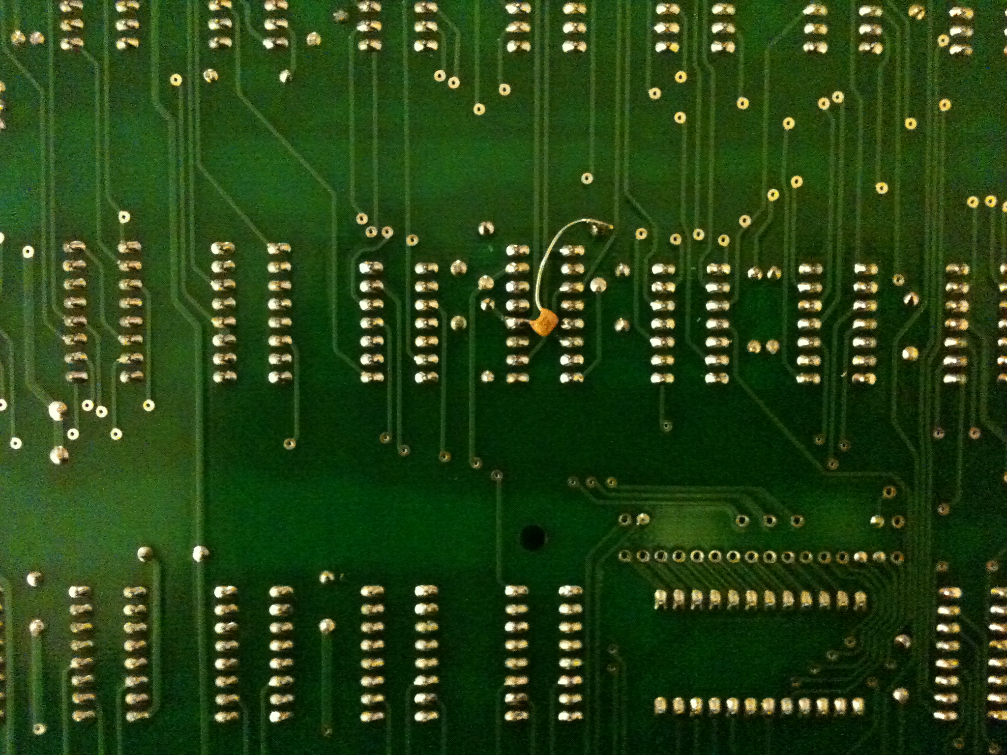
Lionel has tested a fix that involves adding decoupling caps to the -5v supply in the area of the negative supply regulators and around the 2504s. Here is Lionel’s report:
Hi Mike,
Good news!
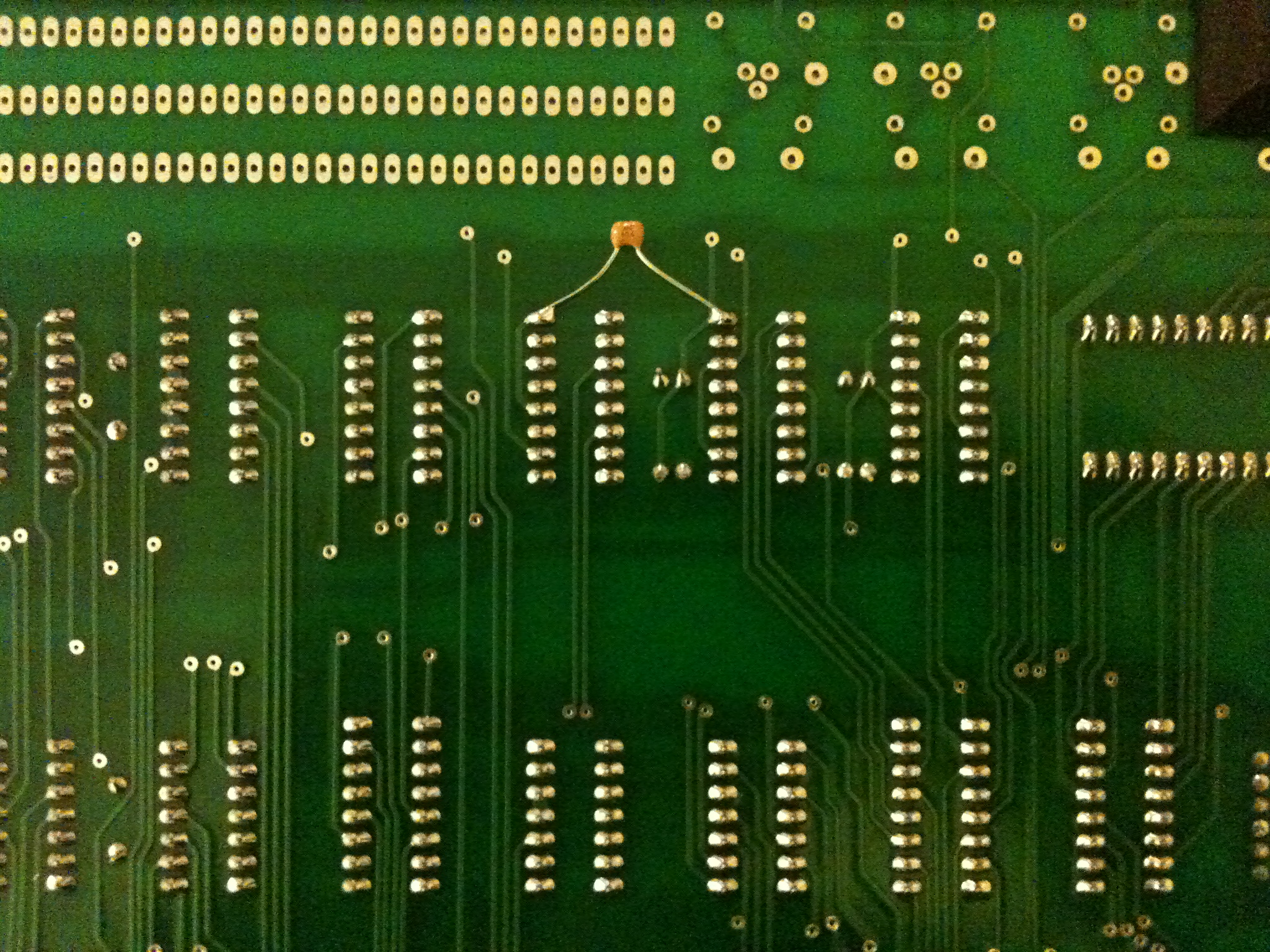
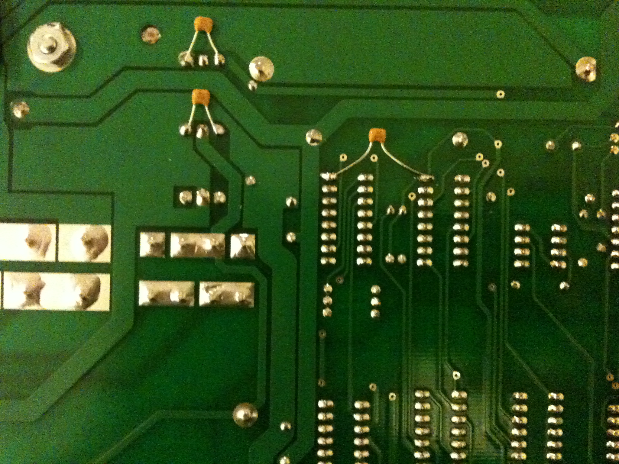
It definitely looks like decoupling the -5V on pin 4 of the 2504’s is the way to go. I’ve added some 0.1uF caps to GND across both the negative regulators, and one on pin 4 of the group of four 2504s at D4-D5, one on the pair at D14, and one on the single 2504 at C11. This cleans up the -5V rail substantially to the point where using the DS0026 works! See attached photos for how I added the capacitors.
Before I did the mod I had a look at pin 4 of each of the 2504s and there was an unbelievable amount of noise on them. It was far higher than what was across the -5V decoupling cap near the RAM. In fact, on the 2504 at C11 there was about 4V p-p of noise, when using the DS0026. I think the switching current of the 2504 must be very high, which in conjunction with the inductance of the traces on the board gives a lot of ringing.
I’ll leave my Mimeo running for a while to burn in and check stability, but so far so good.
Let me know how you go if you try it.
Regards,
Lionel…
Here are a few pictures showing the caps added to the back of the board.
Before Lionel came up with his solution, I tried a fix that involves adding .0022 UF capacitors between the clock outputs of the DS0025 and +5 volt supply. That also helped by softening the edges of the clocks. Lionel’s solution is much preferable, though my attempt did greatly reduce the extent of the video dot problem.
Lionel says Unicorn shipped the DS0026 with the Mimeo parts kit. After contacting Unicorn about the problem, Lionel says that Unicorn has promised to send a replacement DS0025.
SCELBI Debugging Challenges
Experience has shown me that while recreating or restoring vintage computers you frequently encounter unexpected “vintage” problems. Some of these problems were pre-existing and have been forgotten long ago, by the original designers and owners. Other are related to using very old equipment that may have degraded or failed, while sitting on the shelf.
A few months ago, Cameron Cooper was discussing a problem of this type with me. It was related to a SRAM failure on an original SCELBI 8B that he was trying to get back into operating condition. What was most difficult about this debug effort was that the SRAM card could not be debugged with a scope very well, because it was buried between other boards. What he needed was a extender card. I knew I would also need one at some point in the future, so I designed one and sent Cameron the Gerber files, who had several made. Laying out this card only took a couple of hours. The hardest part was finding the correct edge connector, which Cameron managed to do.
Here is the result:
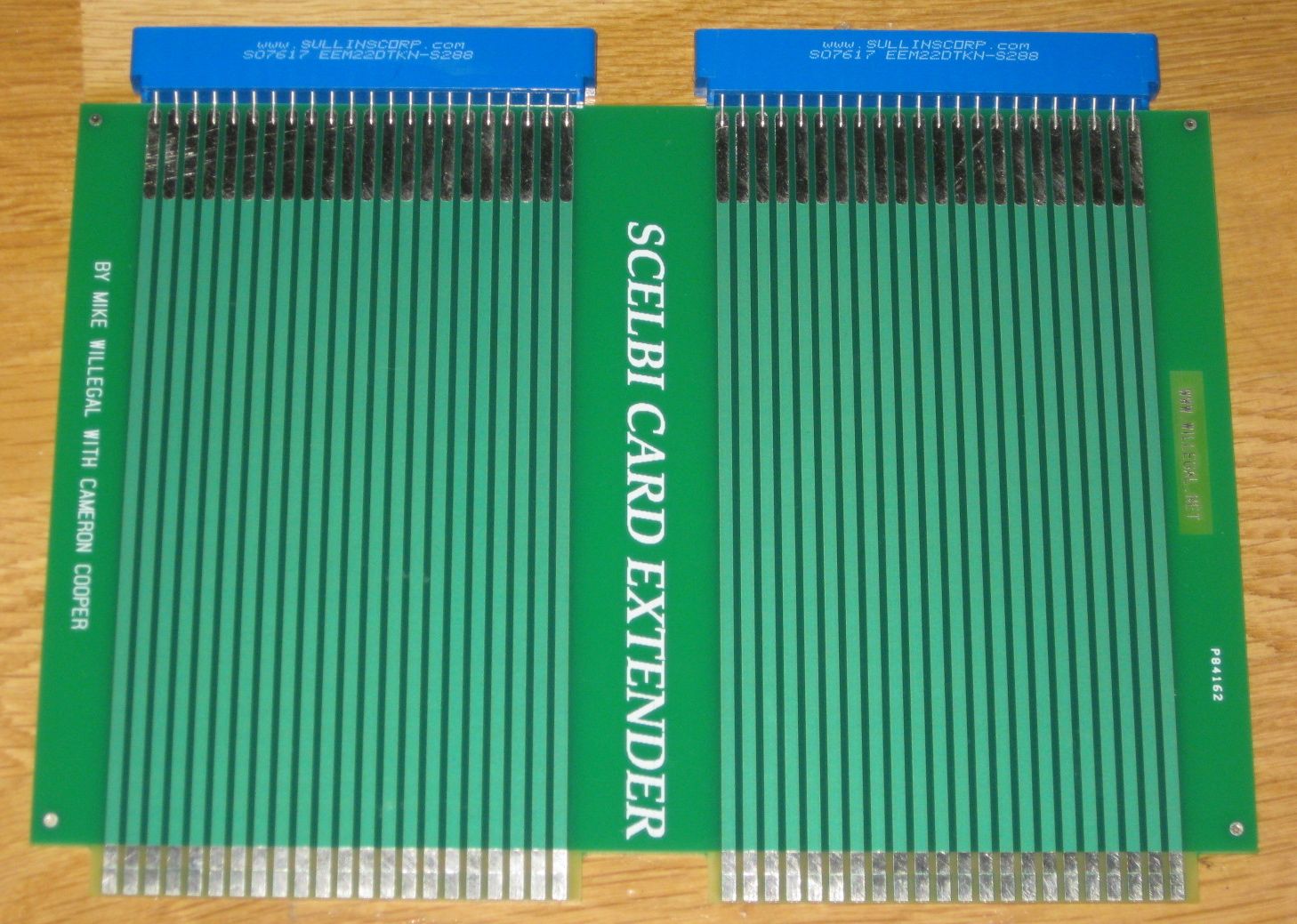
SCELBI card extender
There are other options, that could have been pursued. The SCELBI was originally built on pairs of 4.5″x6.5″ vector cards, mounted side by side. These cards are still available and Vector even sells an extender card.
http://www.vectorelect.com/Product/Extenders/3690.htm
A couple of these cards mounted side by side should work as a SCELBI extender. The main downside of this approach, is that these sell for around $45 each at Digikey, making the cost about $90. This is why we ended up making our own. With the connectors, our cost was about $60 each. The interesting part of this approach is that if we ever need a 4.5×6.5 vector board extender, we only need to cut the SCELBI extender in half.
There is a third option. That is connecting extension wires to the signals of interest on the board under test that extend to the outside of the chassis where you can pick up the signals with your test equipment.
There was one other advantage to making this extender card with Cameron. He was able to check dimensions of the finished board against his original SCELBI, confirming that I had it right.
SCELBI bill of materials for PCBs
Attached is a scan of the original SCELBI bill of materials for the boards and a consolidated version in excell format. I forget where I got the scan, and apoligize in advance for not giving credit to the person that did this work. I haven’t checked for accuracy, but it “feels” right.
The hardest part to find is the 8008, though there always seem to be a few on ebay (at crazy prices). I plan on offering a bundled 8008D as an extra cost option with PCB sets. The D part is a package type, not a speed option. Most original SCELBIs had C package type, but they are harder to find (and more expensive). American Microsemiconductor has thousands of 1101s in stock at good prices (under $4). I have some extra 1101s, and may offer a bundle of 8 as an extra cost option. 74XX parts are available from unicorn electronics in PA.
Each memory board supports up to 4 banks of 8 chips each bank, for a maximum total of 32 chips per board (1K of memory). You can add up to 4 memory boards into a 8H for a maximum of 128 chips and 4K of memory. The minimum is 1 bank of 8 chips on 1 SRAM board for a total of 8 chips and 256 bytes.
You need 6K of memory to run SCELBI BASIC, so it is not possible on a normal 8H. I’ve already started development of the additional/different 4 boards needed for a SCELBI 8B, which can run SCELBI BASIC. The 4 additional boards are a different backplane, 4K SRAM board, memory expansion board and a PROM board. The CPU, DBB, INPUT and front panel are exactly the same for both 8H and 8B systems.
I’m currently looking at edge connector options and will post information on that and other chassis parts in a few days. The edge connector is .156 pin spacing and .140 row spacing, same as Apple 1, though you want ears and longer pins, if possible. Some wires are connected to the edge connector from the back side of the backplane, which makes longer pins desirable.
Here is an interesting bit of trivia – not including the chassis components, the 8 boards making up a fully populated 4K SCELBI 8H require 587 individual components compared to 221 making up an Apple 1 motherboard populated with 8K and 278 making up a 48K Apple II, rev 0.
SCELBI PCBs on order!!!
I’ll bet that some of you thought that this would never happen. I just ordered a batch of six different PCBs that will enable building the SCELBI 8H. I started on the first board about 15 months ago. Comparing to the Mimeo, which I did in 4 months, this has been a huge task.
CPU
DATA BUS BUFFER
INPUT
FRONT PANEL
1K SRAM
BACKPLANE
I plan to offer a limited number of prototype sets at a significant discount for people that have built up one of my other boards in the past. These will be untested boards that will be shipped to you as soon as I get them in, before I have done complete bring and test, myself.
I’ll announce a price in a few days.
Now to get my act together and get the rest of the components that I need for bringup.
Stay tuned,
Mike W.
Further SCELBI 8H Power Supply Considerations
Since I’m almost to the point of building my prototype SCELBI, I have to figure out how I’m going to power the SCELBI during initial bring up. While, later on, I intend to put together a linear supply similar to what SCELBI sold, for now I’m going to make do with more modern supplies. First thing to do is to look at requirements.
The SCELBI 8H requires two supplies, +5 volts and -9 volts. Here is what the SCELBI “ASSEMBLY AND INSTALLATION INSTRUCTIONS AND SYSTEM DOCUMENTATION” says about power requirements.
“CONNECTION OF THE POWER SUPPLY
THE SCELBI-SH MINI-COMPUTER REQUIRES A POWER SUPPLY CAPABLE OF DELIVERING +5 VOLTS AND -9 VOLTS (PLUS OR MINUS 2%.) THE CURRENT REQUIREMENTS OF THE SUPPLY DEPEND ON THE AMOUNT OF MEMORY IN THE SYSTEM (AND ANY ADDITIONAL PERIPHERAL UNITS WHICH MAY BE CONNECTED TO THE SUPPLY.) THE AMOUNT OF CURRENT THAT THE POWER SUPPLY MUST BE CAPABLE OF DELIVERING WHILE MAINTAINING ADEQUATE VOLTAGE REGULATION BE DETERMINED FROM THE FOLLOWING DATA.
THE BASIC SCELBI CARD SET CONSISTING OF ONE EACH OF: SCELBI #1100 CPU CARD, SCELBI #1101 DBB & OUTPUT CARD, SCELBI #1102 INPUT CARD, AND SCELBI #1104 FRONT PANEL CARD; REQUIRES A MAXIMUM OF 1.5 AMPS AT +5 VOLTS AND 100 MILLIAMPERES OF -9 VOLTS.
EACH “PAGE” OF MEMORY IN THE SYSTEM (256 WORDS) REQUIRES 200 MILLIAMPERES OF +5 VOLTS AND -9 VOLTS.
THE CURRENT REQUIREMENTS FOR ANY ADDITIONAL PERIPHERAL UNITS UTILIZING THE POWER SUPPLY MUST BE ADDED TO OBTAIN THE TOTAL CURRENT THAT THE POWER SUPPLY MUST PROVIDE.
FOR EXAMPLE: A BASIC SCELBI-8H EQUIPPED WITH 1024 WORDS OF MEMORY
(4 PAGES) REQUIRES: 1.5 A + (4 X .2 AMPS) = 2.3 AMPS OF +5 VOLTS AND
.1 A + (4 X .2 AMPS) = .9 AMPS OF -9 VOLTS.”
Now, as far as the -9 volt supply goes, this rating appears to be very conservative, at least on paper. There are only two ICs that use -9 volts on the SCELBI 8H, the 8008 processor, and the 1101 SRAM. Reading the spec sheet shows that the 8008 consumes a max of 60 milliamps and the 1101 SRAM a max of 19 milliamps per chip. Typical values are 30 milliamp for the 8008 and 13 milliamps for the 1101.
If the spec sheets are correct, then the base board set would typically draw 30 and max of 60 milliamps. Each page of SRAM would typically draw 13×8 = 104 and max of 19×8 = 152 milliamps. My initial bring up will involve the 4 base board set and 1 SRAM card with 4 banks populated. Max value for this setup is calculated as 152×4 = 608 + 60 or 668 milliamps. The 900 milliamps SCELBI recommends for this config, would give plenty of margin, and just to make choosing a supply easier, I’ll round up to see if I can find a minimum of a 1 amp supply for the -9 volts. Since typical values of a system with 1K might be around 104×4 + 30 = 446 milliamps, I may actually be able to power 2K of SRAM with a 1 AMP -9 volt supply.
The same calculation on the 5 volt supply is much more involved, since it literally involves counting current consumption of every component in the system, so I’ll go with SCELBI recommendations of 2.3 AMPS, but for sanities sake I’ll round up to 3 AMPs as a minimum for the 5 volt supply.
This is for initial bring up. Eventually I’ll want to test a fully populated system, with accessories. Once I have bring up done, I can measure actual consumption and increase power supply requirements based on measured values. Just in case I can start with with power supplies that will handle a full system at initial bring up, I’ll use SCELBI’s recommendations to calculate requirements for a full 4K, 8H system.
That would be 16 pages x 200 milliamps of 5v and -9v for memory, plus the base of 100 milliamps of -9 and 1.5 amps for 5 volts. Total would be 16 pages x.2 amps = 3.2 amps + .1 = 3.3 amps for -9 volts. For 5 volts, 16 pages x .2 amps = 3.2 amps and +1.5 amps = 4.7 amps. I’ll round up the 3.3 AMPs of -9 volts to 4 AMPs and 4.7 AMPS of 5 volts to 5 AMPS.
Ok, so now I know requirements for 8H power supply for bring up and and have a target for full system testing.
Minimum (bring up) for -9 volts is 1 AMP and full system is 4 AMPs
Minimum (bring up) for 5 volts is 3 AMPs and full system is 5 AMPs
What is the most practical way to provide +5 and -9 volts, at these power levels.
I actually have all the components in my Mimeo parts stash, except the -9 regulator, to build a linear supply that would meet this requirement. I actually have the -9 volt regulator, but it would have to stripped off my 1101 SRAM tester.
There are some downsides to this approach as it uses up some hard to find Mimeo parts, it would not be sufficient for a 4K 8H system, and it would take some time to put together and test.
To me, the best answer, is to use off the shelf variable “bench” power supplies. These will be useful for a number of other projects down the road and decent ones provide readouts on current consumption, which a basic homemade supply will not provide. I did a little investigation and there is an easy way to supply both positive and negative voltages to a circuit, if you have a couple of bench supplies with “floating” outputs. Here is a link to BK Precision’s description about how to do it.
http://kb.bkprecision.com/questions.php?questionid=224

Micronta 22-123
For initial bring up, I need 2 bench power supplies (or a single dual supply) with floating outputs for bring up. I already have an old Micronta 22-123 1 AMP 0-25 volt variable DC supply. I’ve had this supply so long, that I don’t even know when or where I got it. It’s been through the wars, having been repaired a number of times. For a long time it operated intermittently, but a year or two ago, I reflowed the solder on the power transistor pins, and it’s been solid, since. Since it will supply 1 AMP, it should work as the -9 volt supply for bring up, assuming that it has floating outputs. Even though I’ve had it a long time, I’ve always run it independently of other power supplies, so I wasn’t sure about that.
After failing to find a manual online, I checked for connectivity between the AC plug and the terminals and there was none. This was a good sign. To prove that the outputs were floating I connected the plus side to the ground on an Apple II motherboard. I connected this through a 5 ohm, 5 watt power resistor to the negative terminal of the power supply. Since the resistor was rated at 5 watts, I could run 1 AMP through the 5 ohm resistance when the power supply was set to 5 volts. This would give me a good indication that I could supply the SCELBI at -9 volts at 1 AMP with this power supply. Next, I connected a voltmeter on each side of the resistor, so I could measure current and voltage.
Before turning on the Apple II or power supply, I cranked the voltage on the power supply all the way down. Now I turned on the Apple II and started running a 2102 SRAM test, that I already had it set up to run. I made sure that it was running correctly and turned on the Micronta 22-123 power supply with crossed fingers. Nothing happened, as I hoped. I made sure the Apple II continued to run the SRAM test, before starting to turn up the voltage. Everything performed as expected, the supply providing 1 AMP of current at -5 volts with no problems, at all. The Apple continued to run the SRAM test, with no glitches. It appears that this supply will work fine as the bring up -9 volt supply. Half the bring up power supply problem is solved.
The other half of the power supply problem is deciding upon a new bench supply to support 5 volts. I’ll blog about my decision process in an upcoming post.