I used this 99 cent design from the web to build a basic ESR tester.
https://archive.today/301HS
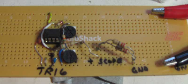
After building and testing it on a solderless, plug in bread-board, I transferred it to a more permanent soldered PCB.

99 Cent ESR Tester
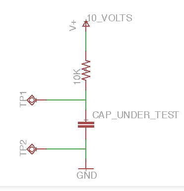
The idea of this design is that capacitors all have inherent resistance. This resistance can be determined by sending a fairly high frequency sine wave through the capacitor, as except for the internal resistance, a capacitor of more than a couple of uF will act like a short. The resistance can be calculated by putting the capacitor in parallel with a known resistance and using the formula for resistors in parallel.
1/R1 + 1/R2 = 1/Rtotal
Though a proper ESR tester uses a sine wave, the square wave which this circuit generates, is good enough for purposes of basically determining if a capacitor’s internal resistance is higher than expected.
I used a 10 ohm resistor in parallel with the capacitor. If the capacitors resistance is pretty high at 10 ohms, then the amplitude of the square wave, as seen on a scope at the input to both the 10 ohm resistor and the capacitor, will be halved. A low ESR of say 1 ohm will result in the amplitude of the wave decreasing by 90%. A higher resistance, such as 100 ohm will have little effect on the amplitude of the square wave. So, depending upon the specification of the capacitor, you can determine if behavior is as expected or not. Most capacitors will have a low ESR of say 1 ohm or less, which results in a dramatically reduced amplitude when attached in parallel with the 10 ohm resistor.
Here is the tester connected to a capacitor.
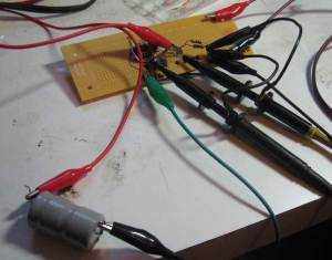
99 Cent ESR Tester Operating
There are a few connections required to operate this tester, but they are easy to make. I connected a bench supply on the right side and adjusted to 9 volts. The capacitor is connected with alligator clips on each side of the 10 ohm resistor, making sure the polarity is correct. The oscilliscope trigger input is connected to the 555 trigger. The oscilloscope channel A is connected to the high side of the capacitor and 10 ohm resistor, which is used to read the result. This circuit could also be used to test a capacitor without removing it from the circuit.
A few notes about my build – the schematic for the 555 timer version of this tester is missing 555 pin 1 connection to ground. Though the design is adjustable, I set up my tester to run at 100 kHz. Higher frequencies would be needed for capacitors below a few uFarad in value. I didn’t have a 10 ohm resistor handy, so I connected 2 22 ohm resistors in parallel to get an effective 11 ohm resistor. This value could be adjusted higher or lower to get better readings on higher or lower value ESR capacitors. The size of the square wave you are measuring is only a few 10s of millivolts so you will need to set the vertical scale on your scope appropriately. I used 10X probes, but 1X probes would result in better resolution. My cost was actually zero, as I had all the parts to build this in scrap bins.