Scopewriter Fail – reason

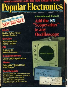
First of all – what is a Scopewriter? It was a circuit intended to make use of an oscilloscope for a single line terminal display. It can take 6 bit ASCII character input and display up to 32 characters on an Oscilloscope. The complete design, with PCB layout, was published in Popular Electronics in 1974.

Radio Electronics cover

Radio Electronics cover

I got interested in building one, thinking it would make a nice accessory for the Scelbi Mini-computer replica that I am planning on building. It is supposed to support a single line/32 character display. There is some documentation available, showing how to interface a Scelbi to a Scopewriter. I thought it also might make a nice display at VCF east.

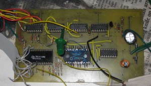
So, using the PCB layout in the magazine I etched a PCB and acquired parts. Most parts were easily obtainable. However, the TMS2501, TMS3112 and the 1N750A zener diodes were hard to find. Eventually I found a TMS3112 in the UK. I tried buying a TMS2501 on ebay, but it turned out to be out of stock. Finally, I figured out that I could substitue a GI 2513 for the TMS2501 with some rewiring. I did a cross reference of the 1N750A zener diode and decided that a 1N5230 should work in place of it.

Next, I built it up and connected a PS/2 keyboard. So far, so good.

Scopewriter PCB

Scopewriter PCB

The problems started with the first debug session. I powered it up and connected the scope, hoping I would get lucky and get to see a line of characters, but nothing intelligible could be deciphered. After mucking around for a few hours, I found some mistakes in the 2513 wiring that I had hacked together to make the GI part work in this circuit. I fixed that and when the display didn’t improve and I called it a night.

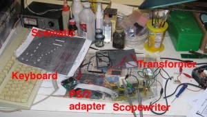
Next debug session, I found that the 3 bit counter selecting the row on the 2513 didn’t look right, but couldn’t figure out the reason. I also noticed that the power supply design, wasn’t the best in the world, with a .5 volt 60 HZ wave showing on the +5 volt line. I did figure out that I had my keyboard adapter wired wrong and fixed that. At this point I could see that characters were being entered into the shift register correctly, but I still didn’t see a good display. After some hours of probing with an oscilloscope, I figured out that the GI 2513 character ROM addressing was different from the TMS2513 and that the bottom line of each character would be truncated when using the GI part. I decided that I could live with that for now. At this point, I was pretty frustrated, by continual problems, on what I originally thought, would be a simple project. I put the Scopewriter aside for a couple of months.

Scopewriter setup

Scopewriter setup

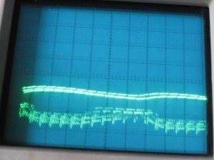
Last night I took it out again and figured out that the counter feeding row select to the 2513, worked better, if I changed a resistor in the the source clock generation circuit. Finally, if I put the same character in every position in the shift register, I could see the display of something approximating characters. Certain characters like “F” were easier to identify than others. However the display was only about 18 characters wide, unless I slowed down the scope to the point where the phosper wouldn’t persist for an entire sweep. Unfortunately, at that slow sweep speed, the display becomes unreadable.. Also the output was not stable, which I attributed to the unstable +5 volt supply.

Scopewriter Display

Scopewriter Display

The display of “F”s in this image actually looks a little worse than the actual display because the camera caught several scans in this single image.

Anyway, when I about wrapped things up last night, something broke in the power suppy, which is the point at which I stopped and sent my last nights blog entry and decided that this project would require several mods in order to work well.

  • base clock speed would have to be increased
  • the clock timing circuit resistor change needed reviewing
  • power supply would have to be improved
  • the 2513 addressing would have to changed make the bottom line visable
  • whatever broke, would have to be repaired
  • This morning, in order to take the pictures for the blog, I found the problem with the power supply. It turned out to be the 1N5230 zerner that had failed. I have a nagging fear that this substitute zerner is the root of many of my problems, so I’ll review specs again. I replaced the zener and took the pictures of the display for this blog entry.

    This has been one of the most stubborn, problem filled retro projects that I have ever worked on – hence the FAIL message. I’m going to put this project away again – maybe I’ll pick it up again some day.

    Scelbi Layout Started

    It looks like I’ll be putting the per cycle Scelbi emulator on hold for a while, since I just started on this:

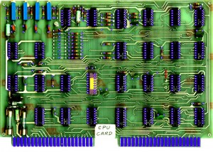
    first draft of IC, resistor and cap placement

    first draft of IC, resistor and cap placement

    This is what the first rough draft of IC, resistor and cap placement for a replica Scelbi CPU card looks like. In the past, once I’ve started on layout, everything else usually goes on hold for a number of months.

    Scelbi/8008 OS/X Emulator Updated

    Several serious bugs resolved including:

  • A problem with the 8008 subtract instruction that didn’t correct set the carry bit. This prevented Scebal Basic programs from being larger than 256 bytes.
  • Several problems with serial input/output that could cause pasted or typed input and/or output from behaving correctly
  • Max paste buffer size was increased to 4k bytes, in order to allow pasting of complete or at least large portions of BASIC programs directly into the emulator
  • For instructions and download links see my previous post:http://www.willegal.net/blog/?p=1705

    For fun, try booting up Scebal and running this program:http://99-bottles-of-beer.net/language-scelbal-2472.html

    I’ve also been working on the per cycle emulator so that I can make the emulated toggle switches and leds work correctly.

    Scelbi 8H/8B- looking for information

    I’ve been bitten by the Scelbi bug and am working with a small team of folks to seriously investigate the possibilities of doing a limited edition reproduction of the Scelbi 8H and/or 8B.

    Data mining on internet and preliminary “networking” has yielded some good scans of the the main plug in cards, some schematics, scans of the Scelbal manual, etc. However I’m still looking for more information, in particular detailed information on the following.

    1)power supply
    2)TTY interface
    3)cassette interface
    4)the oscilloscope output interface
    4)backplane and I/O connections
    5)software
    6)differences between the 8H and 8B
    7)ROM cards
    8)main and expansion enclosures
    9)documentation

    If you have any information on any of the above, or want to contribute in other ways, let me know.

    While we gather information, I will continue to work on the Mac OS/X 8008/Scelbi emulator. See my recent blog post for information on this emulator.

    http://www.willegal.net/blog/?p=1705

    Version 0.1 (pre-alpha) OS/X Scelbi emulator available

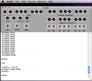
    For the past several months, I have been working on a Scelbi/8008 emulator for Mac OS/X. Here is the first published screen shot of the running app. In this shot it is running Scelbal (Scelbi 8008 Basic).

    Scelbi App version 0.1 Screen Shot

    Scelbi App version 0.1 Screen Shot


    At this time, there are currently 5 mostly working controls available with this app. All other controls either do nothing or react unpredictably.

  • The Memory->Clear menu function will clear 8008 memory to zeros
  • The Memory->Load menu function can be used to load 8008 memory with an intel hex formatted file. I have a copy of scelbal (Scelbi Basic) in this format available to download here. Other 8008 programs could be loaded, but the current assumption is that the PC is set to location 0x40 during reset.
  • The “INT” button will stop and reset the 8008, setting registers to zero, except for the program counter which is initialized to 0x0040. This is not the authentic use of the button, but it was handy for the initial bare bones implementation of this emulator
  • The “RUN” button will start the 8008, or if it is already running, do nothing.
  • The terminal section at the bottom of the window emulates a bit banged serial interface compatible with drivers commonly found with Scelbal. Input is expected to be in upper case. If this window does not respond to input, either the 8008 is stopped, or not currently monitoring the serial port or you have found a bug in the app. Note that unlike a real serial port, input to the port from the keyboard is queued to a length of 256 characters. Overflow conditions are not currently handled gracefully.

    You can download a copy of this app and try it for yourself, but keep in mind that the app is in early prototype stage. It is likely to behave unpredictably, hang and/or crash from time to time.

    The Scelbi/8008 emulation app can be downloaded from here.

    To run Scelbal (basic), do the following.

  • start the Scelbi app
  • clear 8008 memory (optional)
  • load 8008 memory with Scelbal.hex
  • click on the “RUN” button – you should see a “READY” message
  • type “SCR” – this clear’s Scelbal variables – if you don’t do this before entering your program weird things will start happening
  • you can now enter a basic program or basic commands directly
  • Be aware that there are several common 2 character error messages in Scelbal including “BG” for two big and “SY” for syntax error.

    The performance is throttled to approximately actual speed of a 500kHZ 8008. Try executing a “FOR” loop of 0 to 100 to get an idea of the incredibly slow performance of an 8008 running Scelbal. The first version of the 8008 emulator that I had running in a Unix shell environment was approximately 500 times faster than an actual 8008, and even that felt slow!

    The current implementation emulates the 8008 instruction by instruction. If I find the time and energy, I’ll convert it to a cycle accurate emulation and complete the hook up the Scelbi front panel depicted at the top of the app’s window.

    Have fun with it and be sure to let me know what you think.

    Whacky 8008/Scelbi Emulator Project

    Before I actually build a pilot batch of the Hobby cards that I have been designing, I need some pilot projects to try it out with.

    One of these projects is kind of off the wall. I’m working on an 8008/Scelbi emulator that runs in a Unix type shell. Eventually I’ll port this to the 6502 and be able to run it on the Apple II. The 1MHZ 6502 in the Apple II is well over 5 times faster than an 500KHZ 8008, so this isn’t as crazy as it first seems.

    Eventually a brain board version seems like it would make sense. In order to get the full Scelbi effect, I’ll also need to build a replica Scelbi front panel. This is where the hobby board comes in – as the hobby board becomes the interface to the replica Scelbi front panel from the Apple II runing the Scelbi emulator in the brain board. wow -I’ll be surprised if anyone made sense of that last statement when they first read it.

    If you don’t know what a Scelbi is, check out the wikipedia entry.