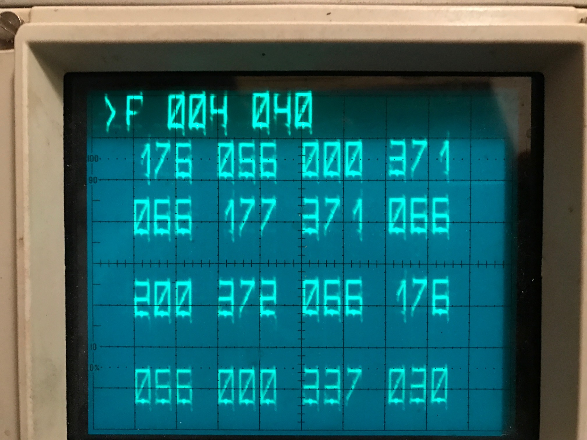
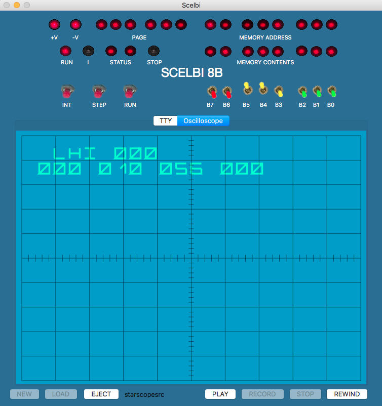
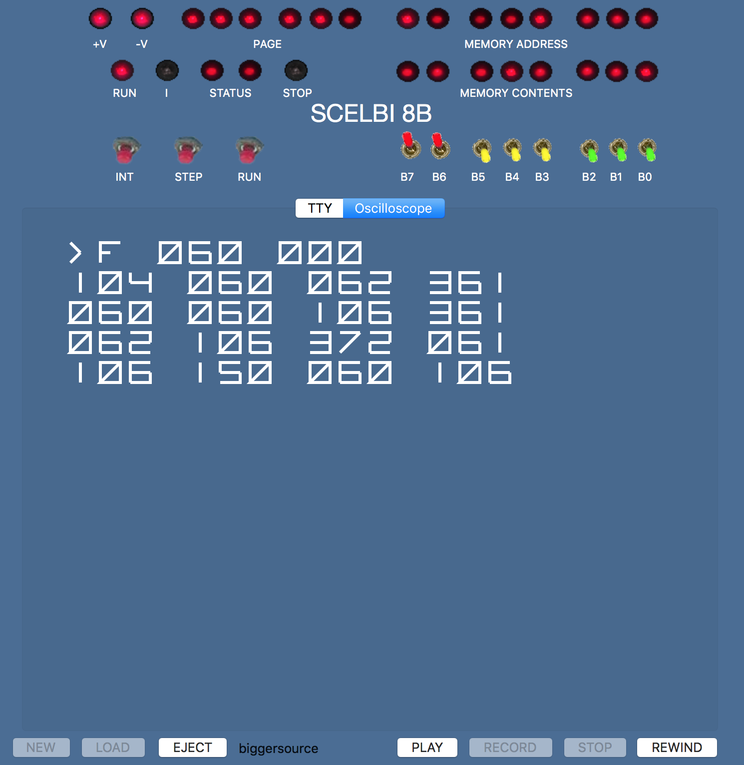
It pretty much works just like the manual suggests. Since it’s faster than the TTY, for tiny programs, it’s actually easier to use.
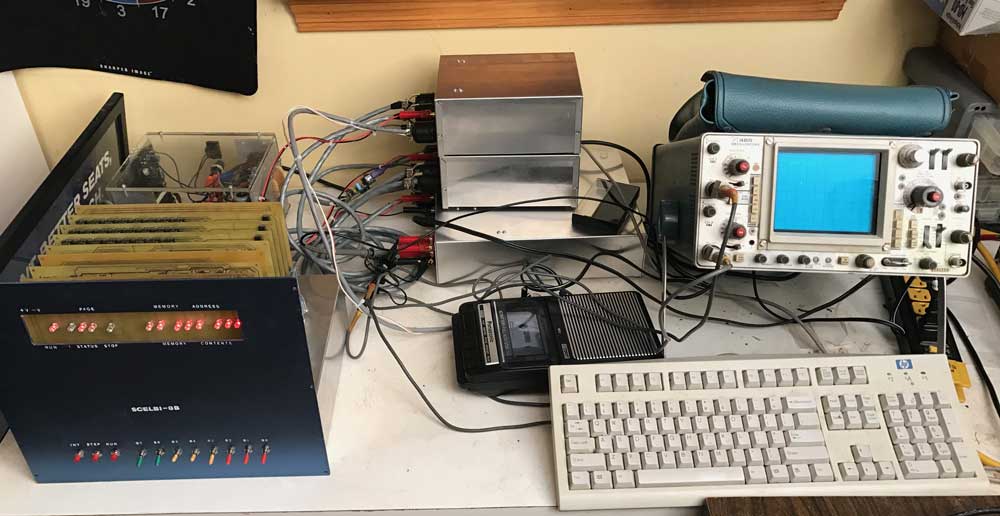
MEA with Oscilloscope Interface
At this point, I’m working on a port of Starshooter. I plan to be able to demo it at VCF east. By that time, I should have the source moved over to the MEA environment, so you can assemble and run the program, natively.
Since the MEA scope driver seems to work OK and the original code can’t be found, here is a source listing for Page 76 of the Scope driver for MEA. Hopefully this version doesn’t get lost in the future.
AS8 assembler for intel 8008, t.e.jones Version 1.0
Options: listfile=1 debug=0 binaryout=0 singlelist=0
octalnums=1 markascii=1
Infile=oscope-pg76.asm
Assembly Performed: Sun Jan 22 14:21:20 2017
Line Addr. CodeBytes Source Line
—- —— ———– ———————————-
1 ;
2 ; SUBROUTINES & MAINLINE TASKS AND A RAM
3 ;
4 ;
5 KEYIN: EQU 004 ; INPUT CHAR from KEYBOARD – MSB set if valid character
6 KEYOUT: EQU 012 ; ACK keyboard interface
7
8 OSCP0: EQU 8 ; SCOPE OUTPUT 0
9 OSCP1: EQU 9 ; SCOPE OUTPUT 1
10
11 ; TERMINAL DEPENDENT CONSTANTS
12 WIDTH: EQU 110 ; PRINTER WIDTH IN OCTAL
13 CR: EQU 15 ; CAR RET CHAR C ASC 1 I Cf\= 1 S
14 LF: EQU 12 ; LINE FEED CHAR (ASC I I LF=1 2>
15 ESC: EQU 175 ; ENTER COMMAND HOOE C ASCI I ESC= 17S )
16 ETX: EQU 3 ; CONTROL C EXIT TO STRT .
17 C: EQU 103 ; REQUIRED TO ECHO ETXr – c
18 UPARR0: EQU 136 ; REQUIRED TO ECHO ETX, -c
19 BLANK: EQU 040 ; space char
20
21
22 BUFFSZ: EQU 310
23 NUMCHR: EQU 151
24
25 NUMROW: EQU 5
26 NUMCOL: EQU 20
27
28 ORG 000#174 ; shared MEA variables
29 00-174 LNPTR: DATA *1 ; output pointer
30 00-175 ADPTR: DATA *2 ; used to clear screen memory
31
32
33 ORG 001#000
34 01-000 BUFFER: DATA *210
35
36 01-322 COLUM: DATA *1
37 01-323 ROM: DATA *1
38
39 ORG 076#000
40 ; ASCII TABLE OF DATA
41 ASCTAB:
42 76-000 000 000 DATA 000,000 ; @ – starburst
43 76-002 340 037 DATA 340,037 ; A
44 76-004 214 037 DATA 214,037 ; B
45 76-006 230 177 DATA 230,177 ; C
46 76-010 206 037 DATA 206,037 ; D
47 76-012 230 037 DATA 230,037 ; E
48 76-014 370 137 DATA 370,137 ; F
49 76-016 210 077 DATA 210,077 ; G
50
51 76-020 344 037 DATA 344,037 ; H
52 76-022 233 173 DATA 233,173 ; I
53 76-024 273 173 DATA 273,173 ; J
54 76-026 374 125 DATA 374,125 ; K
55 76-030 234 177 DATA 234,177 ; L
56 76-032 344 155 DATA 344,155 ; M
57 76-034 344 147 DATA 344,147 ; N
58 76-036 200 177 DATA 200,177 ; O
59
60 76-040 360 037 DATA 360,037 ; P
61 76-042 200 167 DATA 200,167 ; Q
62 76-044 360 027 DATA 360,027 ; R
63 76-046 211 037 DATA 211,037 ; S
64 76-050 373 173 DATA 373,173 ; T
65 76-052 204 177 DATA 204,177 ; U
66 76-054 174 175 DATA 174,175 ; V
67 76-056 144 167 DATA 144,167 ; W
68
69 76-060 177 145 DATA 177,145 ; X
70 76-062 177 155 DATA 177,155 ; Y
71 76-064 033 175 DATA 033,175 ; Z
72 76-066 230 177 DATA 230,177 ; [
73 76-070 377 147 DATA 377,147 ; \
74 76-072 203 177 DATA 203,177 ; ]
75 76-074 177 167 DATA 177,167 ; ^
76 76-076 237 177 DATA 237,177 ; _
77
78 76-100 377 177 DATA 377,177 ; space
79 76-102 277 173 DATA 277,173 ; !
80 76-104 367 175 DATA 367,175 ; ”
81 76-106 343 033 DATA 343,033 ; #
82 76-110 201 033 DATA 201,033 ; $
83 76-112 000 000 DATA 000,000 ; %
84 76-114 000 000 DATA 000,000 ; &
85 76-116 377 157 DATA 377,157 ; ’
86
87 76-120 230 177 DATA 230,177 ; (
88 76-122 203 177 DATA 203,177 ; (
89 76-124 177 000 DATA 177,000 ; *
90 76-126 377 033 DATA 377,033 ; +
91 76-130 177 176 DATA 177,176 ; ,
92 76-132 377 037 DATA 377,037 ; –
93 76-134 377 176 DATA 377,176 ; .
94 76-136 177 175 DATA 177,175 ; /
95
96 76-140 000 175 DATA 000,175 ; 0 – BLOCK 11;61;1 /0 through 9/
97 76-142 377 173 DATA 377,173 ; 1
98 76-144 222 037 DATA 222,037 ; 2
99 76-146 203 037 DATA 203,037 ; 3
100 76-150 345 037 DATA 345,037 ; 4
101 76-152 211 037 DATA 211,037 ; 5
102 76-154 210 037 DATA 210,037 ; 6
103 76-156 173 175 DATA 173,175 ; 7
104
105 76-160 200 037 DATA 200,037 ; 8
106 76-162 341 037 DATA 341,037 ; 9
107 76-164 277 137 DATA 277,137 ; :
108 76-166 177 172 DATA 177,172 ; ;
109 76-170 377 165 DATA 377,165 ; <
110 76-172 277 137 DATA 277,137 ; =
111 76-174 177 157 DATA 177,157 ; >
112 76-176 000 000 DATA 000,000 ; ?
113
114
115
116 ;
117 ; HERE IS THE ROUTINE TO READ FROM KEYBOARD INTERFACE
118 ; destroys C & D
119 ; returns character in A
120 INPUT:
121 76-200 346 LEL ; save H and L
122 76-201 335 LDH
123 ; LHI \HB\BUFFER ; buffer ptr into HL – MEA sets H to 1 before calling
124 DISP:
125 76-202 066 000 LLI \LB\BUFFER
126 76-204 016 151 LBI NUMCHR ; counter
127 ;
128 ; first refresh display
129 ;
130 DISP0:
131 76-206 307 LAM ;
132 76-207 121 OUT OSCP0 ; output first byte to port 0
133 76-210 060 INL ;
134 76-211 307 LAM
135 76-212 123 OUT OSCP1 ; output second byte to port 1
136 76-213 060 INL
137 76-214 011 DCB ; end of buffer?
138 76-215 110 206 076 JFZ DISP0 ; no, continue
139 ;
140 ; now check keyboard for input
141 ;
142 76-220 111 INP KEYIN ; read keyboard
143 76-221 240 NDA ; set sign if a new character present
144 76-222 120 202 076 JFS DISP ; no new character – continue refreshing display
145 ;
146 ; got a character
147 ;
148 76-225 125 OUT KEYOUT ; ack character read
149 76-226 364 LLE
150 76-227 353 LHD
151 76-230 007 RET
152 ; NDI 177 ; clear MSB
153 ; JMP OUTRET
154
155 ORG 076#232 ; echo entry point
156 ECHO:
157 76-232 104 235 076 JMP OUTPUT
158
159 ORG 076#235 ; write entry point
160 ;
161 ; conserves L,B and A, H = 0 on exit
162 ;
163 OUTPUT:
164 76-235 074 237 CPI 237 ; control character?
165 76-237 043 RTC ; yes, just exit
166 76-240 320 LCA ; save character
167 76-241 346 LEL ; save L
168 // LDH
169 76-242 044 077 NDI 077 ; STRIP 2 MSBS
170 ; lookup codes put into A and B
171 76-244 056 076 LHI \HB\ASCTAB ; POINT AT BEGINNING OF ASCTAB
172 76-246 002 RLC ; multiply by two
173 76-247 360 LLA ; becomes index into table
174 76-250 307 LAM ; fetch first byte
175 76-251 060 INL ; point to second byte
176 76-252 337 LDM ; fetch second byte
177
178 ; fetch and increment output buffer pointer
179 76-253 056 000 LHI \HB\ADPTR ; POINT to add location
180 76-255 066 175 LLI \LB\ADPTR
181 76-257 367 LLM
182 76-260 056 001 LHI \HB\BUFFER ; high
183 76-262 370 LMA ; SAVE high byte
184 76-263 060 INL
185 76-264 373 LMD ; save low byte
186
187 ; set up pointer for next write
188 76-265 056 000 LHI \HB\ADPTR ; POINT to add location
189 76-267 066 175 LLI \LB\ADPTR
190 76-271 337 LDM ; fetch out ptr
191 76-272 030 IND
192 76-273 030 IND
193 76-274 373 LMD ; increment it
194 76-275 302 LAC ; restore char
195 76-276 364 LLE ; restore H and L
196 76-277 007 RET ; return
197
198
199
200 ; zero entire buffer page
201 INIT1:
202 76-300 076 377 LMI 377 ; P0 output char to mem
203 INIT2:
204 76-302 060 INL
205 76-303 076 177 LMI 177 ; P1 output char to memory
206 76-305 060 INL
207 76-306 021 DCC ; at end of line?
208 76-307 110 300 076 JFZ INIT1 ; no, branch to continue
209 76-312 076 125 LMI 125 ; P1 output EOL
210 76-314 026 025 LCI 025 ; 21 characters (including EOL)
211 76-316 041 DCE
212 76-317 110 302 076 JFZ INIT2
213
214 76-322 060 INL
215 76-323 076 200 LMI 200 ; end of page
216 76-325 007 RET
217
218
219 ORG 076#343 ; init or clear screen entry point
220
221 ; caller must have H set up point to page zero
222 ; D must contain starting point of init function
223 INIT:
224 76-343 066 174 LLI \LB\LNPTR ;
225 76-345 307 LAM ; fetch start pointer
226 76-346 046 005 LEI 5 ; default 5 lines
227 INITX:
228 76-350 074 052 CPI 052
229 76-352 140 363 076 JTC INIT0 ;
230 76-355 041 DCE ; decrement lines
231 76-356 024 052 SUI 052 ; decrement character count
232 76-360 104 350 076 JMP INITX
233
234 INIT0:
235 76-363 012 RRC ; divide by two
236 76-364 330 LDA ; reduce count by offset
237 76-365 006 024 LAI 024 ; number of characters per line 20
238 76-367 223 SUD
239 76-370 320 LCA
240 76-371 060 INL
241 76-372 367 LLM ; fetch out ptr
242 76-373 050 INH ; point to output buffer
243 76-374 104 300 076 JMP INIT1
244
245 ORG 076#377
246 76-377 300 DATA 300
247
248
249
250
251
Symbol Count: 32
Symbol Oct Val DecVal
—— ——- ——
KEYIN 004 4
KEYOUT 012 10
OSCP0 010 8
OSCP1 011 9
WIDTH 110 72
CR 017 15
LF 014 12
ESC 175 125
ETX 003 3
C 103 67
UPARR0 136 94
BLANK 040 32
BUFFSZ 310 200
NUMCHR 151 105
NUMROW 005 5
NUMCOL 024 20
LNPTR 174 124
ADPTR 175 125
BUFFER 1 000 256
COLUM 1 322 466
ROM 1 323 467
ASCTAB 76 000 15872
INPUT 76 200 16000
DISP 76 202 16002
DISP0 76 206 16006
ECHO 76 232 16026
OUTPUT 76 235 16029
INIT1 76 300 16064
INIT2 76 302 16066
INIT 76 343 16099
INITX 76 350 16104
INIT0 76 363 16115