Keep following this blog as I reveal some details of the repair of an extremely rare computer. I think that this system is currently the only fully operational original system of it’s kind in existence.
After a bunch of effort and a number of replaced parts, I have decided that my Tek 465 might possibly have a bad CRT. I’ve decided to put this repair effort on the back burner and ordered a INSTEK GDS-1054B digital scope. It has 4 channels and 50 MHz speed which should be sufficient for most of my hobby purposes going forward. I’m not real excited by the 50MHz speed, but given the price point that I was shooting for, it was either that or drop down to two channels to get a 100MHz unit at a similar price. I figured that I would use the extra channels more often than the extra speed, so I went with the 4 channel 50MHz unit. One problem is that it doesn’t support Z mode, which means I don’t have a way to run my SCELBI CRT Interface until I either get the Ten 465 working again or get one of my Heathkit OM-14’s restored. Somehow I ended up with three of those Heathkit scopes. I intend to restore two and use the last one for parts.
Finally watch my demonstration of an operating SCELBI-8H with Digital Group Video card at the Virtual VCF that will be shown on youtube tomorrow: .https://www.youtube.com/watch?v=7YoolSAHR5w. I think that this shows that with some effort, the SCELBI-8H can be transformed into a pretty useful computer.
Getting my Tek 465 operating correctly again has been quite an involved exercise and to be honest, I considered giving up on it. As related in my previous post, after replacing a questionable electrolytic capacitor, it didn’t come back to life. What really made me consider giving up, is that the problem appeared to be in the high voltage section that drives the tube, as the power supply started making some buzzing noises and the display disappeared. I don’t have proper probes for handling those high voltages and didn’t want to get myself into a dangerous situation.
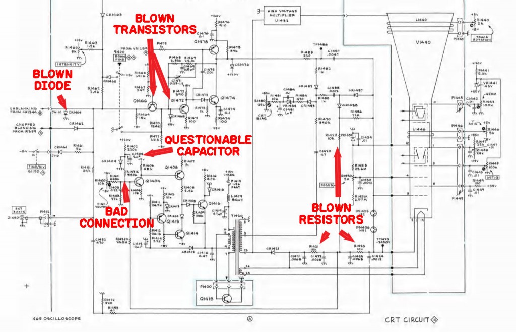
However, before giving up, I decided to take a look, as best I could. With power off and no high voltages present, I did some poking around with a meter, using the diode checker function to check out transistors and diodes and ohm meter to check out resistors. After a lot of probing, I found that 10K resistors R1421, R1422 and R1423 were all open circuit. They must have all blown like fuses.
After replacing them, I found that the scope still had issues. What could have caused all these resistors to fail, I thought. Eventually, after examining many more components, I found that one of the connections to a custom film resistor was open. This was near the capacitor that I had replaced. I think it must have had marginal contact all along and I must have broken it when replacing that nearby capacitor which connects near one end of this resistor package.
465 Woes
This resistor is used in the high voltage switching supply as part of the feedback circuit. I think this open connection caused the supply to run away and generate too high a voltage which caused the buzzing noise and must have blown out the resistors.
Fixing this contact and replacing the blown 10K resistors seemed to have restored the high voltage as the display now started working and didn’t buzz any more, however horizontal blanking didn’t work correctly. The blanking circuit was less scary to me, as it didn’t involve super high voltages and I dived in.
Probing the blanking circuit, I found two bad transistors, Q1466 and Q1472. It turns out that Q1472 could be replaced by an ordinary 2N3906, but Q1466 used a Tektronix part number 151-223-0. I found that equivalent replacements are either a 2N4275 or 2N5769, depending upon who you believe. However I didn’t have either in stock. I found the same part was used elsewhere in the scope and decided to try a swap to see if I could get further in the debug. It’s convenient that the transistors in this scope are socketed.
After swapping, I found that I still had a problem in this part of the circuit. After much digging, I finally found that diode 1464 was also blown. Well it was actually internally shorted and acting as a low value resistor instead of a diode. This was another part that I didn’t have in my stash, a Tek cross reference page called for a 1n4244. It turns out that this is a diode with a 750 pico second recovery time, rather fast, which I assume is necessary in order to switch the blanking on and off quickly.
At this point, I decided to call it a night and to find correct replacement parts before preceding further. I found that someone in Oregon had the exact Tek part number 151-223-0 for Q1466 and I found another vendor had the 1N4244, though I had to order some additional parts in order to make up a minimum order for this particular order. I have been meaning to build a SCELBI quick loader box and needed some toggle switches for that application, so I tacked an order of 8 toggle switches onto this order to make up the minimum amount.
Last, I swapped back the good 151-223-0 to its original location and set aside the scope. You don’t want to be swapping these parts around willy-nilly, as it can ruin calibration.
It will be interesting to find out if the scope will be finally be made good when the new parts arrive.
My faithful Tektronix 465 scope failed again. This was a repeat of the B trigger holdoff problem, that mysteriously fixed itself a few weeks ago. Of course problems like that usually return and it didn’t take long. This time around, it didn’t fix itself.
I didn’t know much about how this scope worked and I had to spend a considerable amount of time over several sessions before I finally tracked down the root cause. It turns out the triggering circuits of this kind of analog scope are made up of a number of transistors that are often configured to operate over very specific voltage ranges that are set up by resistor divider networks. Frequently diode or gates are used to combine signals, which makes it hard to determine exactly why a signal is behaving the way it is. When something goes wrong, it’s not always obvious to the casual investigator what it might be.
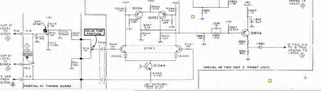
Anyway, I eventually tracked the problem down to a bad transistor in the B trigger holdoff circuit. This is transistor Q1052 in the schematic. I verified the bad transistor by swapping it with Q1054, which is the same type. The nature of the problem changed, indicating that one of the transistors was bad.
B Trigger Holdoff Circuit
The part number listed in the service manual is 151-220-03, but I found another TEK manual with cross references that listed a 2N3906 as a “similar” part. I had some of those on hand, so I swapped out the bad part and B Trigger started working again. Since this seemed like a pretty basic PNP transistor application, I was planning on trying the 2N3906, if the cross reference recommended something else that I didn’t have.
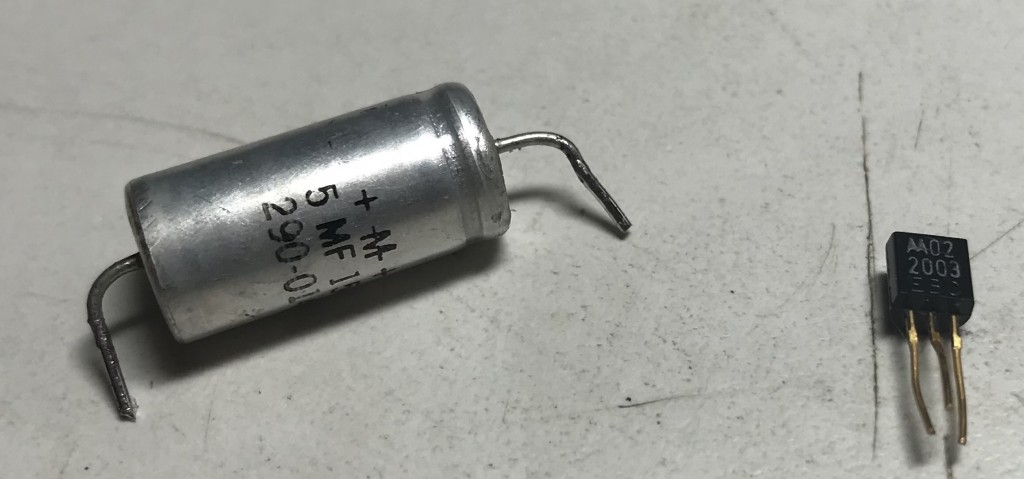
Capacitor and Resistor
During this investigation I noticed an electrolytic capacitor that appeared to have some tarnish near one end. I decided to replace it before putting the scope back together. I looked up the value, and it was a 5 uF cap rated at 150 volts. I searched my stash and found I had nothing that would work in that application. I pulled the part and did some basic checks. It measured at 7uF. I found that resistance was infinity on my meter, although I know that means little. I have a primitive ESR checker, but it requires a working scope, so I couldn’t do that check. A search on Mouser showed that they had something in stock. However, the cost of two parts plus shipping was almost $15, so I decided that maybe the capacitor I had would do ok for now.
After replacing the capacitor, the scope refused to power up, with some apparent problem in the power supply. It made a ticking noise much like an Apple II power supply that doesn’t have a load. I double checked my soldering and could find no issue. At that point I decided to pull the cap again and order a new capacitor and do some research on the power supply before continuing…
My faithful old Tektronix 465 has recently been experiencing issues with the delay function for the secondary horizontal timebase.
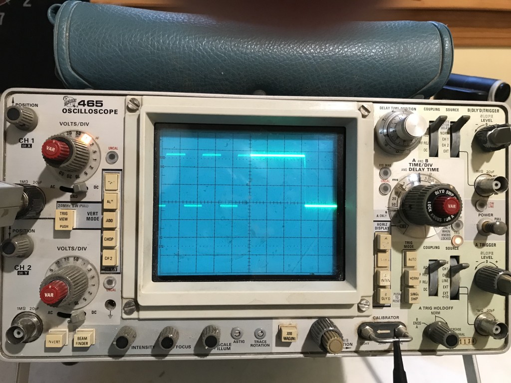
For those not familiar with this feature, here is a quick explanation: the Tek 465 has dual timebases. You can set up timebase A for say 1 millisecond per division and timebase B for say 10 microseconds per division and switch the horizontal timebase from A to B as the raster scans across the screen. This is useful when you want to zoom into the details of a signal sometime after triggering as the raster is partway across the screen. This switch in timebases can be by trigger or by a delay feature.
It’s basically a controllable zoom capability. I find the time delay version of this feature most useful, but recently I found that when the change in timebases was set to delay, it would trigger immediately, instead of delaying.
After several debug sessions, the feature started working intermittently. This slight improvement in behavior started after probing in the area of several suspect transistors. I pulled the most likely transistor out of it’s socket and tested it using a diode tester. It tested good. After reseating it and some other transistors, the feature seems to working reliably again, though only time will tell for sure.
In this demo, the trace of the 1KHz calibrator signal is set up to display at .5 ms per division until half way across the screen, when the timebase switches to 50 us per division. The slower rate of raster movement intensifies the display at the higher speed.
Anyway I took a good look at some relevant signals while it is working, so I’ll have a better shot at debugging it, if the problem crops up again.
There is nothing worse than intermittent sockets and connectors. I’ve had this scope for a long time and it has served me well, but maybe it’s starting to show it’s age a bit. By the way, as I don’t have a second scope, once again, I used this scope to debug it’s own issues.
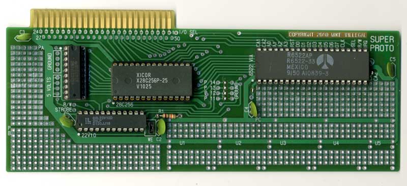
I had a fairly elaborate WIKI dedicated to my Superproto card, but either an upgrade of some underlying support application broke it or it was hacked. After making an effort to recover it, I decided to put up a basic HTML based page which shouldn’t suffer from that sort of issue in the future. Unfortunately, I don’t have time to recreate a lot of the detailed content regarding usage and applications.
I managed to test the version of MCMON for Digital Group Video card on real hardware, but there was a bit of drama involved. I started seeing corrupted characters when running Hangman with this card. From the beginning it looked like a memory issue.
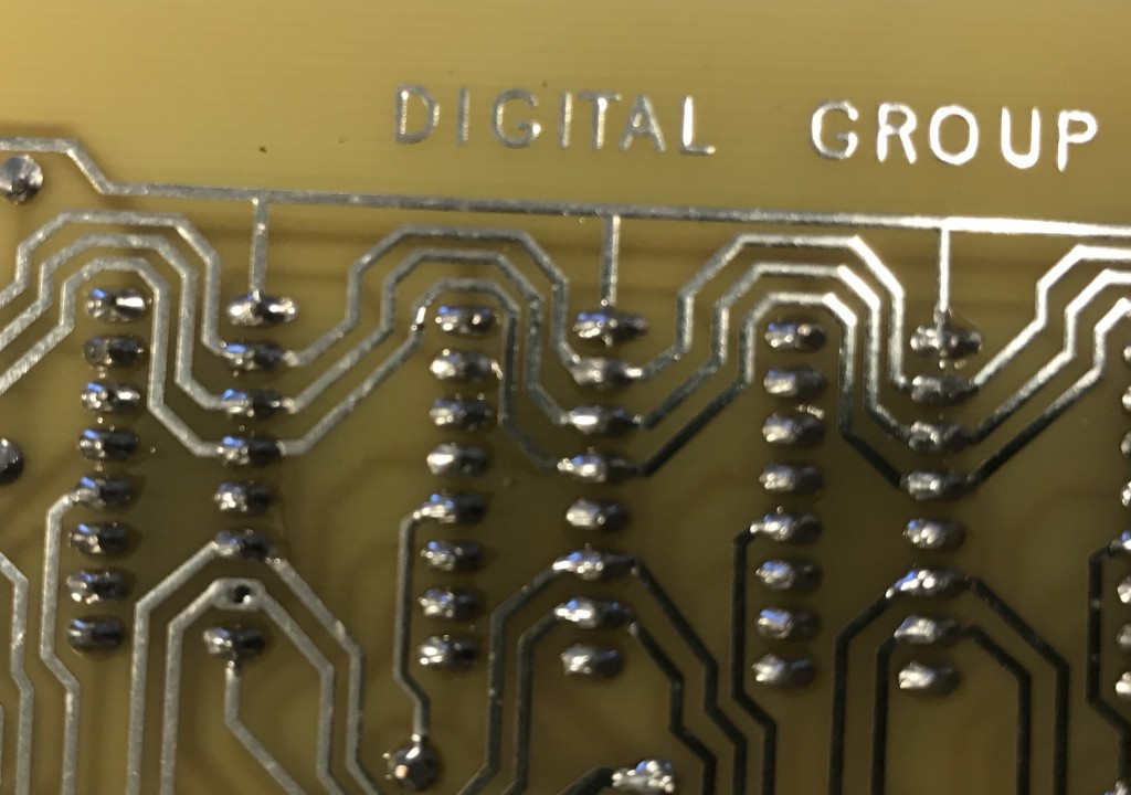
First, I ruled out the problem being in the SCLEBI system memory by stopping the program and examining the local copy of the video buffer which looked correct. Then I took some time to isolate exactly what was wrong with the Digital Group Video Card memory. After closely examining the symptoms and running some simple tests, I determined that the most significant bit of video memory had a problem with adjacent locations. In other words, if I wrote MSB of address 0 to zero or one, then MSB of address 1 would also change to the same value. Same thing happened when writing to address 1. This was true of all pairs of memory locations where the upper six address bits (of seven) were the same.
Digital Group Video Group Card with error
The problem was finally tracked down to a pin that wasn’t soldered which left this address line floating. This turned the 256 bit SRAM chip in that location into a 128 bit chip. Adjacent memory locations were sharing the same data in this chip, accounting for the error.
I didn’t see this problem when testing a full array of characters displayed on the screen or when running MCMON because in those cases all adjacent characters share the same value of the MSB.
With this problem resolved, I was able to verify that Hangman with Digital Group video drivers worked correctly. This software can now be downloaded from my 8008 application page.
My MCMON (8008 mini-monitor) with Digital Group Video support can be downloaded from my MCMON page.
This is version 3.1 of the OS/X SCELBI app and can be downloaded from the usual page.
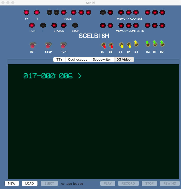
There is only one change in this version. It turns out that when 0xFF is written to it, the actual Digital Group Video hardware, sets the address to 255 and writes 0xFF to memory. The old version of my app just set the address of video memory to 0x0 and did not do the write. I found the discrepancy when testing a new Video MCMON monitor with real hardware.
This leads to a bunch of new stuff that I will be making available over the coming weeks. I will be adding this new DG video version of MCMON to my MCMON download page.
I also have a DG video version of Hangman that just needs final testing on real hardware. This is going to make a great display for the next VCF event that I manage to make it to.
I have crafted a minimal SCELBI cassette read program that is small enough that it can entered in a few minutes with MCMON. This will allow loading of larger programs into the 4K SCELBI-8H, without undo trouble or assistance of another computer. I actually created this a long time ago, but don’t think I ever put it up for download. Going forward, this is how I will be loading Hangman and other apps into my 8H.
By the way, I have to write about how proud I am of the OS/X SCELBI application. It really operates exactly like the real thing and with all the memory and peripheral options I have added, makes a great platform for checking out the 8008 microprocessor and hardware that was available in the mid 1970s.
With the emulated tape, I am able to completely test the process for typing in the tape read driver using MCMON and then loading hangman by tape. I still have to repeat the process on the real hardware, but the emulation has been so good in the past, that I don’t expect problems when repeated with real hardware.
I suppose I might have to build a DG cassette card, so I have more coverage of the available options from back in that day.
As far as the OS/X SCELBI app goes, I’ve started the process of putting the source up on git hub. I don’t know if anyone will take advantage of it, but it will eventually be made available.
Late last year, I wrote an essay about Steve Wozniak and the Apple 1 and Apple II. I think it might be a bit controversial in parts, as when Woz read a draft, he disagreed with a couple of the statements. I have been holding back on publishing, partly because I’m a little concerned about Woz’s comments, but I think it probably should be released anyway. I will take one more shot at editing it, before I put it out, but it’s already in pretty good shape.
Last, for those of you that are interested in the history of SCELBI or early micro-computers, I am working on a essay covering Nat Wadsworth’s life from the time he started SCELBI. Publicly available information on Nat Wadsworth is very limited. A few months ago, I conducted several extensive interviews with Terri Wadsworth, Nat’s widow. She was very open about their lives and provided a lot of insight into Nat Wadsworth’s personality and the history of SCELBI.
I need to follow up with a couple of additional interviews before I can complete this essay and would prefer to do this in person, so it will have to wait until the corona virus runs it course. I am sure that what I have already learned will be very exciting for people really interested in the early days of micro-computers. I just need to fill in a few blank spots before I feel I can release.
This version adds support for the Digital Group Video Board, as well as a ported MCMON monitor for the 8H that works with that interface. The following image is a screen shot of the app, showing the DG Video screen displaying an MCMON prompt.
SCELBI Emulator
This application is freely available for download from my web site.
I’m having a bit of trouble with the Apple Help system, but in case it is not working for you, you can also access the help pages from my web site.
The I/O port mapping for this emulator can be found on the Menu Options page of the help system.
The Digital Group Video Board interface for SCELBI has been one of the longest Vintage Computer projects I have been involved with. You wouldn’t think that fairly simple video card would involve so many different sub projects, but it has been quite an interesting challenge.
That said, I’m not quite done with it, as I still have to put together a nice demo application. That application is planned to be a port of SCELBI hangman. I have started flowcharting the video output software, but have a little ways yet to go.
One interesting thing to note here is that the PDP-8/M solution, though it is more expensive, isn’t orders of magnitude more expensive. It seems to carry a 50% cost disadvantage.
So finally, here is the entire document in one PDF.
Here is where this document really looks more like a product plan more than anything else. This section starts with a statement of availability of prototypes on March ’74 and production unit in June ’74. It follows with statements that no field service will be offered and a warranty period of 90 days. The lack of field service is due to the expectation that the customer will be technically capable, the relatively low cost of the product and high cost of field service contracts.
The next page contains a product promotion and support plan. It mentions several trade magazines, was well as a direct mail campaign. I checked several of the periodicals mentioned and couldn’t find any relevant MPS-10 ads, so I don’t know if they came out later or exactly what happened.
The documentation plan is mentioned, as well as some trade shows.
Given this extensive marketing plan, it is somewhat surprising that so little is known of the MPS-10 today.
The competition section might be the most interesting to vintage computer hobbyist. Among other architectures, the National IMP16 series is mentioned. The IMP16 is classified as a microprogrammed machine, rather than a fixed instruction set, as the 8008 and 8080 and a few others are classified as.
On the next page are listed a number of competitive systems made up from the previously listed microprocessors. Except for the the Microl and Sim-8, most of these systems are little known by the vintage computer hobbyist of today.
There is a chart showing features of the various systems, including the all important development tool support. This section is definitely worth review by the vintage computer hobbyist.