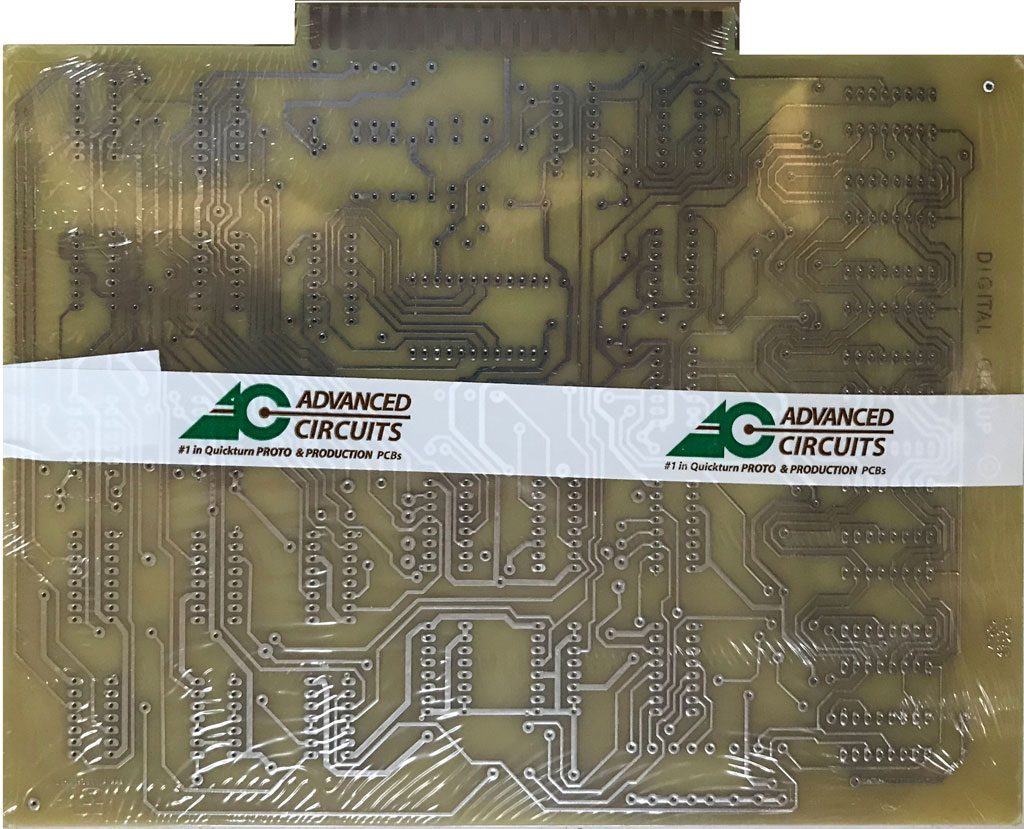
I’ve had the layout done for a while, but haven’t had time to build them. Thinking I might as well get the PCBs made, I finally pulled the trigger.
DG Video Card
As far as building and testing them goes, free time is still scarce, and I will not get the needed 5MHz crystal until early December, but I have the rest of the parts on hand or arriving shortly. I may be able to build them and run them with an external frequency source, so the lack of a crystal may not be a complete show-stopper. It may or may not be quite a while before I get them up and running.
One other thing. I explored getting these boards made in China, but since I had a batch made, the end cost was about the same as using Advanced Circuits. Getting one or two made would be vastly cheaper if I had them done in China, but I always have taken the chance and have reasonable sized batches made.
Original Digital Group Video Cards are scarce, but I don’t believe that the market for these cards will be very big. I expect the 20 that I had made, will cover the demand, plus some.
I finished the reproduction Digital Group Video Card PCB layout a few months ago. This summer, I’ve been busy with other projects, but I’ve finally ordered a batch of PCBs. I should have them in hand in another week or so. I have all components in hand or on order. I’ve found the 5 MhZ crystal is not exactly common. I currently have a few on backorder at Mouser. Expected ship date is early December, so I may not be able to fully check out this card for a while.
I don’t expect the software to be very difficult, as the hardware interface is very basic. If you want to change any characters or do anything like scrolling, it looks like you need to write out the whole page of display data. The easiest thing might be to keep a mirror of video memory in main memory and write out the whole thing anytime that there is a change.
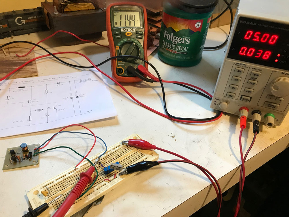
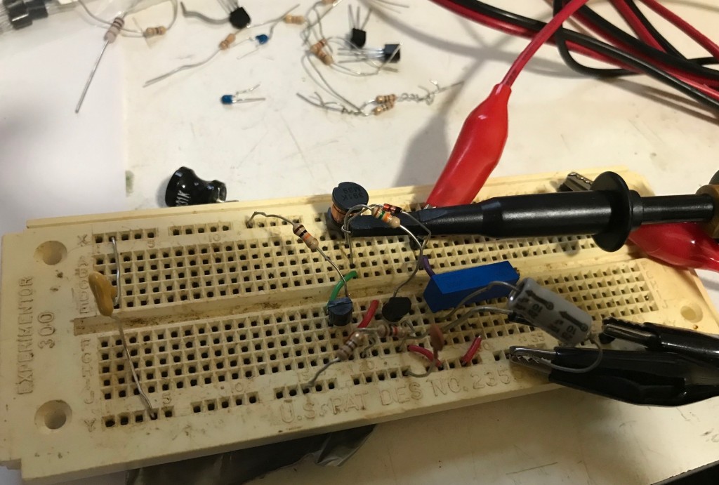
Here is my test setup for the finished DC-DC converter. The power supply supplies 5 volts DC. The bread board includes filter capacitors and a potentiometer that is used to supply a load. These items emulate the final circuit when the DC-DC converter is installed on the Digital Group video card.
DC-DC Converter Under Test
The supply shows that the current draw is 38 milliamps. With the potentiometer set at about 1K ohms resistance, the DC-DC converter is supplying 11.44 volts, which I think will be sufficient for the final application on the Digital Group video card.
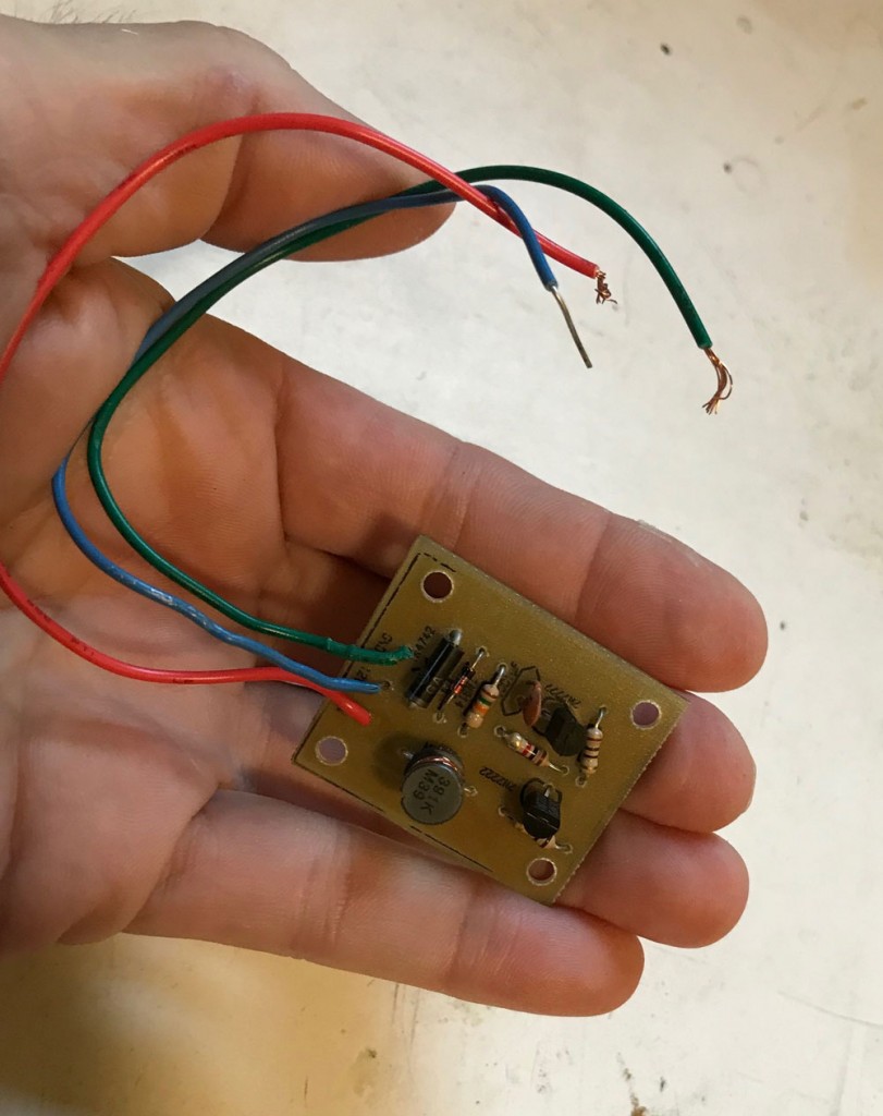
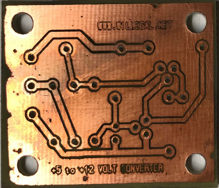
One final comment on this converter. This thing seems very small to me. In fact, when I first made the PCB, I wondered if I had mistakenly scaled it to a smaller than 1:1 size.
Here is the finished board, ready and waiting for a Digital Group video card.
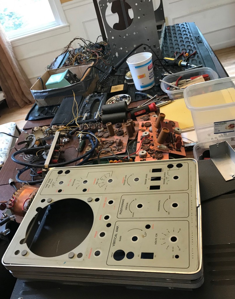
This thing used to be in one piece. I’m pretty sure I’m in over my head on this one. I wonder what the chances are that it will ever work again. The good news is that I have two more copies of this model that are still in one piece that can be used for parts. I also have a manual, which is pretty comprehensive and includes construction instructions.
In a previous post, I have noted that the MCM6571 character generator on the DG video card requires a +12 volt power supply. +12 volts isn’t normally available in a SCELBI computer system. Now that the PCB layout of the DG video card is nearly finished, I took some time to look into building a circuit that could supply the +12 volts for the character generator.
Here are the basic requirements that I came up with for this supply.
According to the data sheet, the MCM6571 requires a 12 volt supply that will supply 8 milliamps of current, worst case.
In order to keep things simple, I think it is best to generate the 12 volts without the use of a transformer or use of mains power. That leaves the 5 volt supply as the source of power to a voltage boost circuit. This circuit would have to boost those 5 volts up to 12 volts. Not being a power supply expert, I hoped I could find a design on the internet that could do this for me.
It turns out that there are lots of modern, inexpensive solutions for generating 12 volts from a USB interface’s 5 volt power, but almost all of those, use modern linear ICs. In order to keep things vintage, I want to use components that were commonly available to hobbyist in the mid 1970s.
Continued searching of the internet revealed a few transistor based solutions. I looked for a design that might be made up from components that I already had in my stash. This would make building a prototype easier and avoid the expense of ordering or spending time looking for parts in the one store we have in my area that stocks electronic components. I picked out a likely design and then searched my stash for the needed components. I managed to find enough parts to put together the circuit on a bread board. Unfortunately, after spending several hours debugging it, I found that I couldn’t get this circuit to work.
I gave up and went back to the internet. A new search revealed a slightly simpler circuit that used many of the same components that I had used on the first circuit. I already had found most of the needed components while building the first prototype. I built this second, similar, circuit in almost no time. After replacing a bad diode, and correcting the orientation of the transistors, which I had inserted backwards, this circuit sprang to life. One thought I had, was that the bad diode probably was the source of the problem with the first circuit. I decided to not to revisit the first design and I pressed onward with this new circuit.
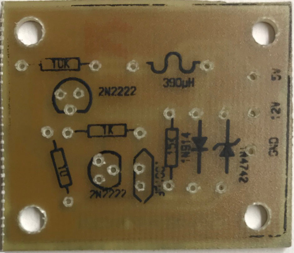
My prototype has a few slight changes in component values. The nearest value inductor I have on hand is rated at 390uH. I didn’t have a 6.8 ohm resister to use for R2, so instead I used a 10 ohm resistor. I used 2n2222 transistors instead of the BC337 specified on the schematic. I used a 1N914 diode instead of the 1N4148, as my understanding is that these are equivalent parts. One other difference is that the zener I had in my stash is rated at 12 volts, not 13.
5 volts to 12 Volts Boost Converter
There are decoupling and smoothing capacitors on my prototype, as shown in the schematic. However, depending upon how I connect it to the DG video board, I may just rely on the DG video card smoothing capacitors that are present on both +5 and + 12 volts. This will allow me to eliminate the 47uF and 10uF capacitors in the final implementation. Should I go this route, this circuit will be composed of only 1 capacitor, 1 inductor, 2 diodes, 2 transistors and 4 resistors. This is a total of only 10 discrete components.
I tested this power supply using a bench supply set to 5 volts as the input voltage. The bench supply was set for a maximum of 200 milliamps current in order to prevent destroying components during debug. It turns out that this voltage converter draws less than 40 milliamps. I tested the output by connecting a 5K ohm trim pot between the output and ground as a load. I adjusted the pot until I could see when output voltage started to significantly decrease. Measuring the resistance on this pot at this setting and using ohms law, I was able to confirm that it should support the power requirements of the MCM6571, and have a little bit of margin to spare.
Since I’m no longer making or selling Brain Boards, I’ve made the Gerber files and CAD files available for download from my website. This board has been cloned by a few different folks, but if you want to make one, it’s easier than ever.
I’m aware that Superproto WIKI is currently broken. I’ve made a couple of half hearted attempts to fix it, and will hopefully find some more time in the near future to properly repair it.
The only hard to find part, should be the MCM6571. I picked up a few, a year ago. I don’t remember off-hand where I got them, but it was probably an eBay purchase.
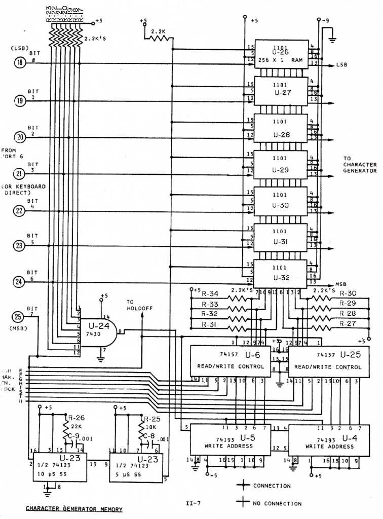
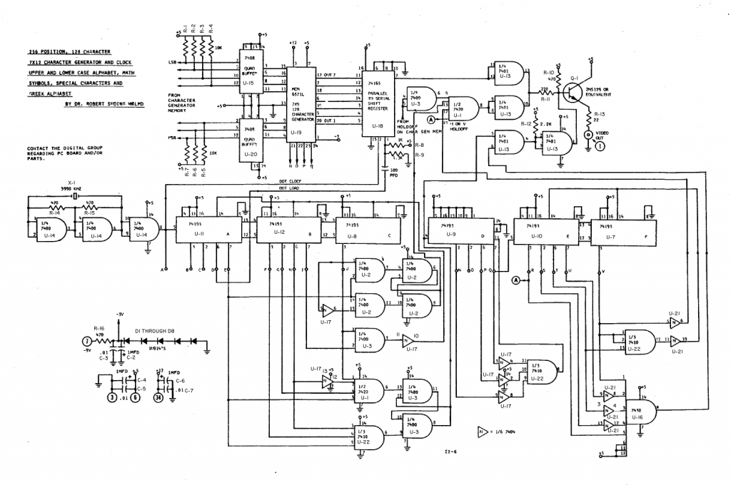
These schematics have part identifiers added to them that match the drawing that I posted yesterday. There are also a couple of corrections. A couple of the connections to the inverters at U-17 and U-21 went to different pins than what was actually connected on the PCB. No functional difference, but it could cause some confusion when debugging. One other thing, there are actually eight voltage dropping diodes, not the five shown on the schematics.
DG Video – Memory SchematicDG Video – Char Gen Schematic
Work on reproduction of this PCB card nearing the end of the CAD phase. I’ve gone through numerous design checks and think that if I had a card made with the current CAD files that I most likely will have all the connections correctly made.
I’m currently going through a final pass of making sure alignment of reproduction traces matches with the original. Though I am close to finalizing those changes, close inspection is still revealing a few adjustments that will improve fidelity to the original design.
Once I get to the point that I can’t find any more tweaks to make, I’ll pull the trigger on getting a small batch of boards made. I expect very limited demand, so this will most likely be the only batch that I make.
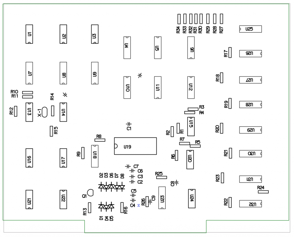
I’ve also created modified schematics that includes part identifiers that match what I’ve done in my CAD program. The original Digital Group schematics do not include any part identifiers. Here is what the board with identifiers currently looks like in my CAD file. Note that chip orientation is not consistent on this board, so anyone building one of these will have to work carefully to make sure chips are not inserted backwards.