Most 8008 based computers are very similar, the CPU, some static memory, maybe some EPROM with a monitor and I/O ports.
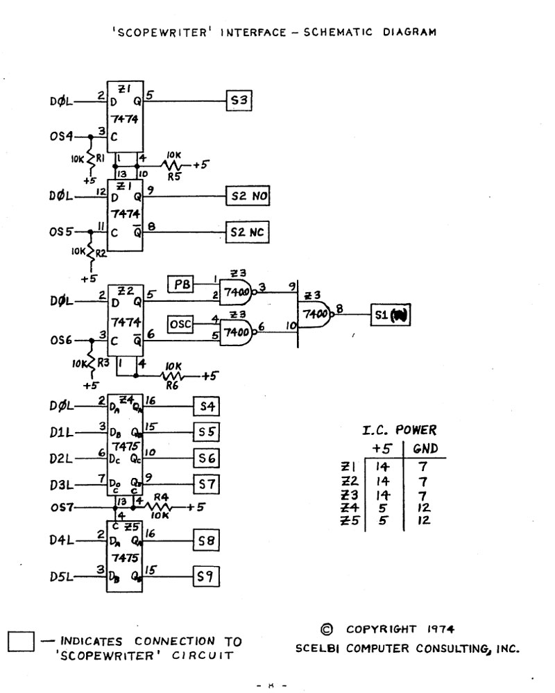
The 8 bit I/O instructions of the 8008 lead to very simple hardware interfaces. Typical interfaces include serial “bit banged” ports, where is single output and a single input bit is tied to a simple current loop or RS232 level interface. The other basic type is a parallel byte oriented interface, where bytes are sent to the output ports and latched by external (outside the CPU complex) hardware for use. An example of the latter type would be a UART, which converts a byte of data handed to it, into a serial stream of bits.
Like many programs of the time, most 8008 applications were written for a specific hardware platform and included drivers for that platform. Example platforms include the Mark-8, SCELBI, Mike, RGS, Microl, and so on.
The driver is the piece of code responsible for moving data between the CPU and whatever peripheral devices are used by that program. Any program of the period will initially be written with drivers appropriate for the platform that that programs original author is using.
Moving programs between these platforms with different I/O interfaces, involves replacing or rewriting the drivers, so the ported program will interface correctly with the hardware on the target platform.
What sometimes makes porting 8008 programs so difficult, is that often, different drivers make different use of the limited register set of the 8008. Programs written for a specific driver will be written to take account of the registers used by the driver. This is so that when the driver is called, the driver does not corrupt any registers that are in use by the main program.
So here’s the problem. Let us say that we are porting a program to a system that requires usage of an extra register in the user input handler program. The person porting the code has to go back to every place in the program that calls the user input driver and make sure that the extra register is available for that driver. Not only that, but any place that calls the routine that calls the driver, also has to take into account how those registers may be affected. With the 8008, this affect tends to cascade though the subroutine call stack, making reservation of a single register more complicated than expected.
For most processors, this isn’t a great big deal. If necessary, the programmer simply saves the register to memory, before calling the driver. However, with the 8008, saving the register requires that you set up H and L registers with the address in memory in which to save the register. If H and L are being used already, this means that not only do you have to save the first register, you first have to save H and L. Saving H and L requires 2 additional registers. To save the original H and L, you need to move them to different registers so that you can put the address of where the original H and L are to be saved into H and L. Then after the driver is called, you may have to restore all the registers back to the original settings.
If you are seriously constrained in total amount of memory, things get worse. An example of a memory constrained program is MCMON, which runs in a single 256 byte EPROM, plus a little bit of SRAM for variable storage. In the MCMON case, adding a bunch of code to save and restore registers everyplace a driver might get called, could could easily end up causing the program size to expand beyond the 256 bytes of available memory. It took considerable amount of work to make MCMON fit in the available space.
On the surface, porting 8008 programs would seem straight forward. In actual practice, I find it far from straight forward, and often a difficult process. I still recall porting the Starshooter game that was documented in an early Byte Magazine article. This game was written for the SCELBI and I was porting to a SCELBI, which would seem simple. However, the original author’s SCELBI must have had an UART, which simplified his drivers. A UART handles all the serialization in the UART chip. My SCELBI only had a bit banged serial interface, which required a more complex driver, which used additional registers. I managed to port the program, but it took me a number of hours to work through all the changes needed to make the game work on my system.