My last update was in December of 2014 and I’ve made a bit of progress on a couple of fronts.
Documentation
I’ve done a substantial amount of work on completely OCRing the original 8B hardware manual. This is the first step of making a new manual for people interested in reproductions. I plan on going through the manual and adding all the information that I’ve accumulated that is relevant to people building reproductions. Much of this information is scattered about over several years of blog posts, emails and in some cases, web pages.
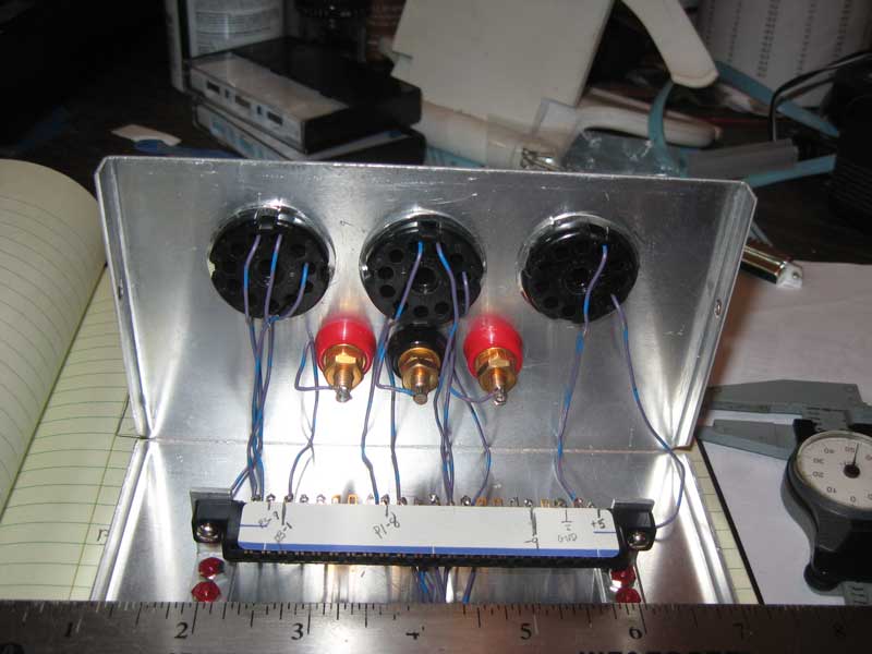
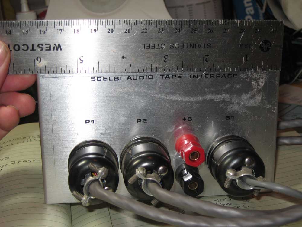
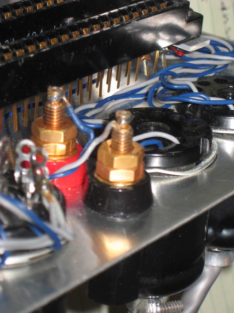
I just started work on putting together a build guide for the cassette interface boards. It will have the look and feel of the other SCELBI construction guides, but as we haven’t found original build instructions, it is new work. Though build instructions are missing, some original documentation on the cassette interface has turned up and that will be OCR’d, as well.
Mechanical
I have built reproductions of the 8H using a BUD AC-413 chassis and the 8B using a custom chassis that Corey had fabricated. I still need to put together reproduction chassis for the peripherals and the power supplies. For those, I’m using off the shelf enclosures of approximate the same dimensions of each type of original enclosure. At one point I was looking into making my own reproduction enclosures, but I haven’t found a good deal on a box and pan brake that is sufficiently capable to handle these jobs, so that idea is on indefinite hold. Screen printing of the 8B front panels should happen in the next week or so.
PCBs
My estimate of getting the cassette boards done in the first half of 2015 was off by a few months, but it did happen in 2015. I do feel a bit bad that the people working on reproduction 8B projects had to wait so long for those cards.
My estimate of getting keyboard and oscilloscope interfaces done in 2015 is not likely to happen, though I expect the fairly simple keyboard card should be done in early 2016 and I hope the oscilloscope cards are done by end of 2016. Both of these cards will take some software work, as no one has come up with original drivers for either.
In all, there were 16 different PCBs made by SCELBI for the 8H and 8B computers and associated peripherals. For quite a while, I’ve dreamed of having reproduced the entire set. It’s hard to believe, but at this point, I’m only three PCBs away from having completed that task. For those that are into numbers, that means that I’m over 81% of the way there!
The current status of my reproduction efforts of each of those cards follows.
Main System Cards – working reproductions of all 10 cards types have been completed.
Reproduced
1100 CPU – 8H/8B
1101 Data bus buffer – 8H/8B
1102 Input – 8H/8B
1103 Backplane – 8H
1104 Front Panel – 8H/8B
1105 1K SRAM – 8H
1106 Memory Expansion – 8B
1107 4K SRAM – 8B
1108 Backplane – 8B
1109 PROM – 8B
Peripheral Cards – 3 reproduced, 1 in progress, 2 haven’t been started.
Reproduced
2102 Audio Tape output
2103 Audio Tape read
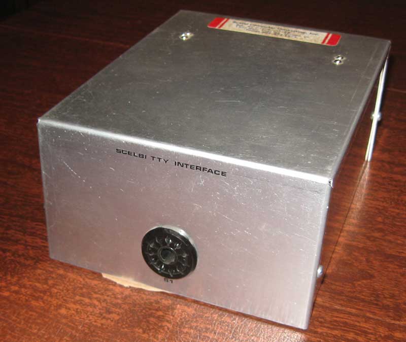
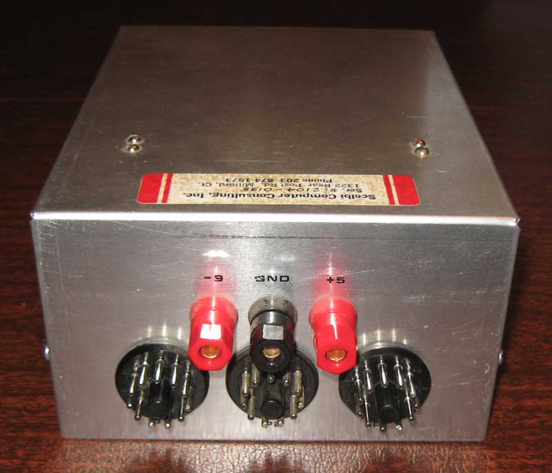
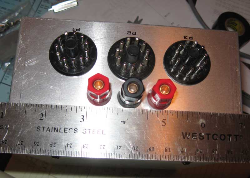
2104 Teletype interface*
In progress
2105 Keyboard
Not started
2100 Oscilloscope digital**
2101 Oscilloscope analog
* not as high as normal vector boards
** double width vector board
