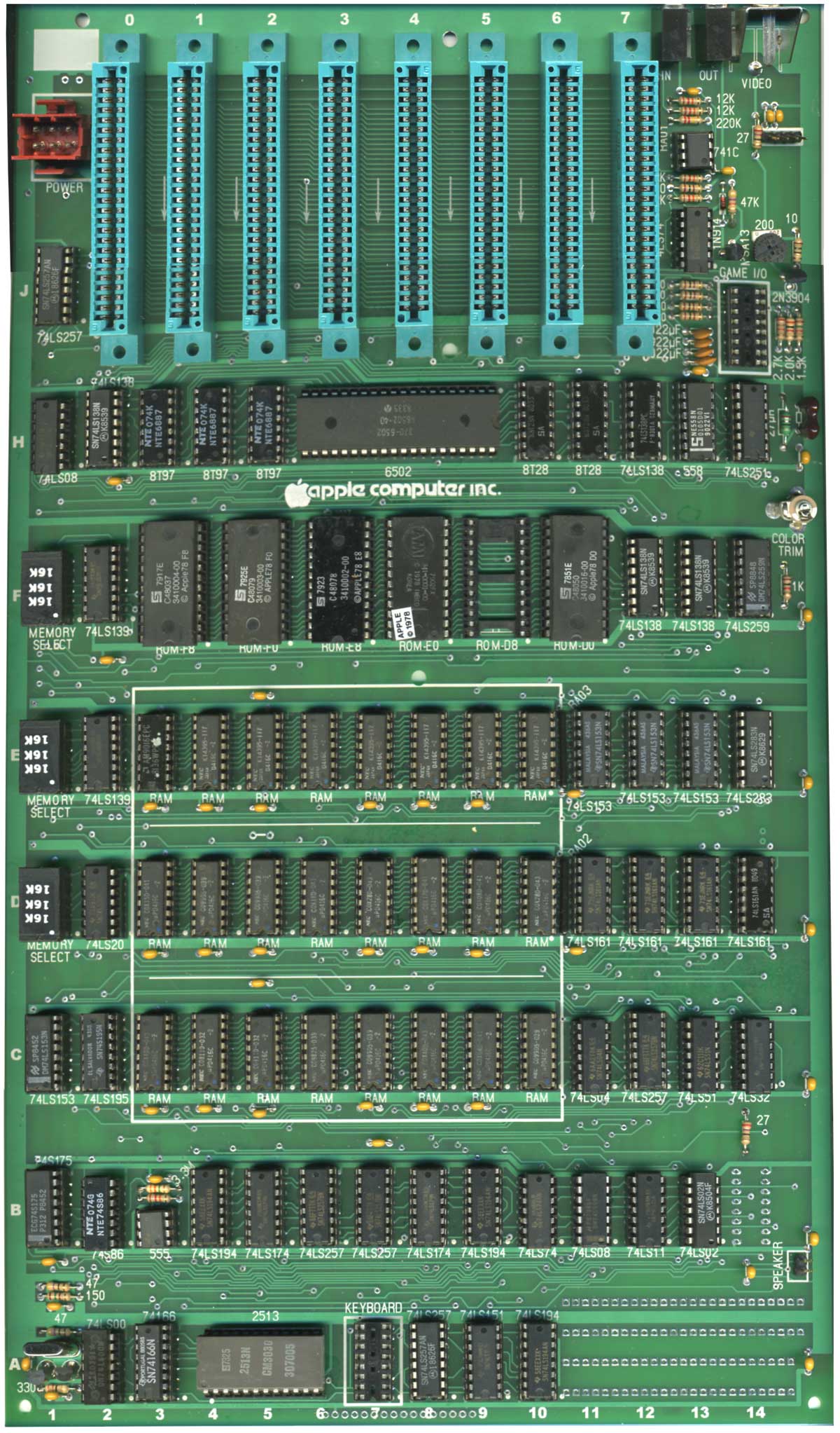
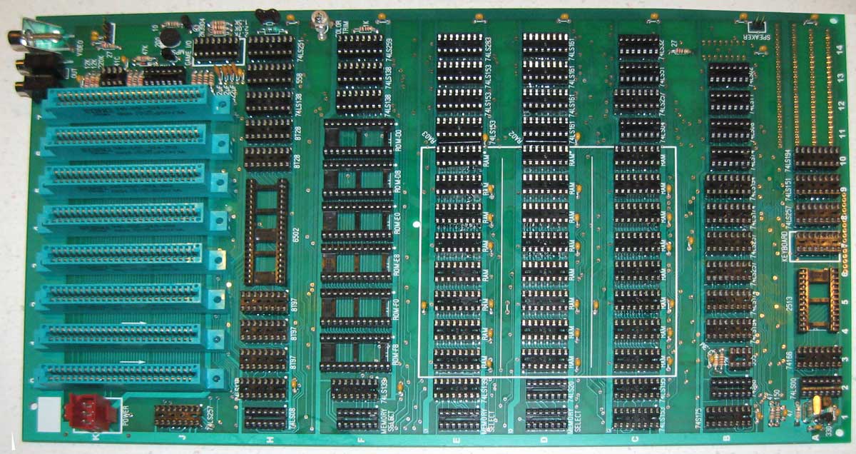
Apple II rev 0 Progress
My revision of my original reproduction, the Apple rev 0, is coming along. This morning, I did an extensive design review of the 35th revision, and only found 3 things that needed “fixing”. I’ll probably repeat the effort tomorrow on revision 36. Hopefully that review passes cleanly. If so, I’ll get quotes, pick a vendor and kick off board fabrication next week.
Projects in the Lab
Like usual I have a lot of other projects in progress. Some have been in progress for while, others not. Here is a snapshot of my workshop. It keeps getting more crowded as time goes on.
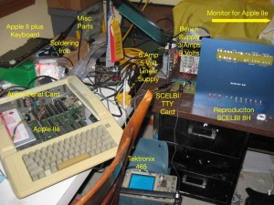
My Retro Workshop
SCELBI TTY CARD UPDATE
My “LAB” is currently setup for checking out the SCELBI TTY card, which is interfaced to an Apple II serial card, which also supports 110 baud current loop. The hardware is working, but I have to do some software work on the Apple II side of the serial current loop connection in order to make it usable. The standard Apple drivers seem just a bit quirky,as they are tied into Apple II monitor functionality. I was hoping to get by with Apple’s standard PROM drivers, but it looks like I’m going to have write a custom driver for interfacing to the SCELBI. I’m hoping to get the IIe running such that it works just like a real TTY, perhaps eventually including emulating paper tape using floppy discs. I decided to use the IIe instead of a II or IIplus because it supports 80 column output without extra plug in cards.
SCELBI Galaxy
I was hoping to make a video of the SCELBI running tiny SCELBAL basic and the SCELBI Galaxy program, which I recently got running. The Galaxy program is SCELBI’s version of the Star Trek game. It was published as documented source code in the SCELBI book “Galaxy”. I had to OCR a scan of the book and then covert it to the AS8 assembler format that I prefer. This took a considerable effort, but I was able to exactly reproduce the original program. When I first went to download it into a physical reproduction 4K SCELBI 8H, I discovered that there wasn’t enough room in memory for a boot loader and the game. I had to spend a lot of time creating a second version the source code to make it fit into 4K with room for a boot loader, without altering the play of the game. This was particularly difficult as the originally published source, didn’t have labels attached to any of the messages, just hard coded addresses pointing into a huge block of characters. In order to move anything in memory, I had to convert the hard coded addresses to labels and add the label to original block of bytes. Oh yeh, there were some page boundary assumptions that I also had to deal with. It wasn’t easy. Once I get the Apple IIe TTY emulation going, I’ll definitely make the video of both the Galaxy game and tiny SCELBAL running on the 8H.
SCELBI Webpage Update Coming
I have an update to my 8008/SCELBI web pages coming. Right now, there is too much on my 8008/SCELBI page and I’ll break it down to a few smaller pages. One page that needs a lot of work is the SCELBI/8008 software page. I have managed to get a number of 8008 programs running, some new and others, like Galaxy, old programs that I believe haven’t been run in decades. I need to set up a dedicated software page in order to share them all, plus the cross development tools that I have used to develop them. Most 8008 software from the era will need to have I/O drivers tweaked in order to run in a particular environment, so I will need to publish source and tools. Some of the software, I didn’t develop, so I need to get permission from creators. I would also like to find time to covert my SCELBI blog posts, along with original documention into some kind of book form, as information about building a SCELBI is rather scattered around. I don’t know when or if I will get around to this, but I am motivated, as I think better documentation might help me to sell more SCELBI board sets.
Apple IIplus
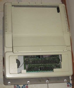
Apple IIplus
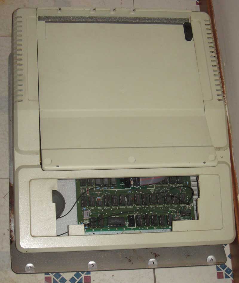
At top of the first picture you can see the keyboard for an Apple II plus that I recently picked up as part of a Craig’s list transaction. My intention is to clean up and repair this Apple IIplus for resale. I think it will make a good first II plus system for someone, since it has a pretty late serial number along with an RFI board. My experience with those later systems with RFI boards is that they tend to be more reliable than earlier systems. In fact, except for some keyboard issues, this system came in working condition. As you can see by comparing the inside of the top with the rest of the case, the plastic hasn’t yellowed much, if at all, so it should clean up real nicely.
TRS-80

TRS-80
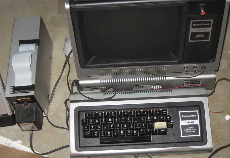
Along with the IIplus, I picked up a TRS-80 system, with expansion chassis and floppy drive, along with documentation. It doesn’t work, but it should be a fun project to fix up. I can’t decide whether I will keep or flip it. Initially I was going to add it to my collection, but the engineering isn’t what I’m used to, so I’ve already somewhat soured on it. A friend of mine had a TRS-80 briefly, back in the 70’s, but took it back and got an Apple II. Having played with his TRS-80 briefly in the 70s, is what spurred my interest in having one, now. If I keep it, I’ll need to get a Commodore Pet in order to have one of each of the first machines of the “big three” computer manufacturers of the 70’s.
I keep telling people that I’m not a serious collector, as I like to work on, learn about and operate these old machines. I don’t usually acquire vintage computers, just to own, which is a sign of a serious collector. However, as you can see from this blog post, I seem to continually find ways to increase my “backlog” of projects.

