7/7 is the 40th Anniversary of Nat Wadsworth running the first program on the first SCELBI. Thanks to Mark Arnold for reminding me of this.
Regards,
Mike Willegal

7/7 is the 40th Anniversary of Nat Wadsworth running the first program on the first SCELBI. Thanks to Mark Arnold for reminding me of this.
Regards,
Mike Willegal
happy 4th of July..
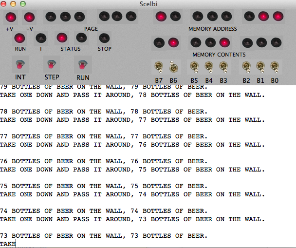
SCELBI app
I think I have front panel controls working now
download the app with this link
Scelbi.zip
cheat – load scelbal and hit the run button to see blinking lights
Scelbal.hex
web page and some notes can be found here
http://www.willegal.net/scelbi/the8008andScelbi.html
Constructive feedback welcome.
regards,
Mike W.
I now have SCELBI TTY cards in stock and will ship one to you for $30, shipping included. If you are interested send an email to: mike@willegal.net. Be aware that at this point they are not tested, so until I get one tested, I don’t guarantee that they will work without modification.
Regarding TTY card testing, I have been delayed because I didn’t have a current loop interface to test it against. Well that has been rectified, as I have the Apple II Serial Card that I mentioned in another post working (at least in RS232 mode). In order to get that card working in a way that would work for interfacing to the SCELBI TTY card, I had to reconstruct and burn a P9 PROM that matched the first version PROM. Wendell Sander was nice enough to send me a PROM that was a copy of his serial card P9 PROM. However, his P9 PROM was overwritten in a couple of spots with a all ones pattern. I took his PROM and compared the parts that were intact with the listing at the back of the manual and determined that I could resurrect his PROM by filling in the missing code with the code from the listing in the manual. After messing up my first attempt, I burned what I thought was a good P9 PROM. I put it in the Serial card and tested in RS232 mode against a Super Serial card in another Apple II. That simple test was successful and I now have a working Apple II Serial card without the undesirable flow control behaviors of the second version PROM.
I should be able to use this card in current loop mode for testing the SCELBI TTY card. In fact, I have visions of putting it in an APPPLE IIe (for the needed 72 column support) and emulating TTY operation as closely as I can with the Apple II. I should be able to emulate not only print and typing functions, but emulate paper tape as well. Potentially, I could even add a real paper tape reader and possibly punch by constucting an interface on a SUPERPROTO board.
As far as my prototype TTY card itself, it is mostly built up, just missing a couple of resistors which should arrive today or tomorrow. Once it’s together and tested I’ll put up a Bill of Materials, some simple build instructions and photos.
Check out this article in the San Jose Mercury News. I never thought that this would be the result when Ralph Simpson, a volunteer for the History San Jose museum contacted me for tips on bringing up their Apple 1. I put him in touch with Wendell Sander and Dan Kottke and the rest is “news”. Note that there were several Apple 1s present that are not in my registry. Probably an indication of how many are still out there in the wild, unaccounted for.
It also shows why I don’t count working Apple 1s anymore. Ever since it was determined that working 1s were far more valuable than non-working 1’s, everyone is fixing them up. In a way, this is great, as we originally noted that there weren’t many that were operating, anymore. We thought it was a bad thing that so many were not powered up and being used. My point of view has shifted a little bit, since there are quality reproductions out there, that can be operated instead, and the value of the originals has gone through the roof, maybe running those old machines doesn’t make as much sense, as it used to. That said, so far, I haven’t heard of one being damaged by power up, so why not run them and keep them working.
There is another small number that is interesting, though. There are not very many left in the hands of original owners. Original owner, Wendell Sander asked me this question, and I could only come up with a few, though I’m guessing that there are more out there in the “wild”, still in the hands of original owners. I’m not giving a count, but it definitely seems like a small number.
Also Bob Luther is launching a book on the Apple 1. His kickstarter is almost over, but it sounds like it will be available elsewhere, afterward. I was interviewed by one of Bob’s assistants a couple of years ago, so this book has been in the works for a while. It will be interesting to read what Bob has found out about the Apple 1.
I’m calling version .97, my beta version.
Update – this version has errors in the definition of the ROL and ROR instructions – replaced by http://www.willegal.net/blog/?p=6454
Apple/Mimeo 1 people, be aware that normal production and stocking of MPS3704 seems to have stopped with major distributers. I just received this email from Mouser.
Hello Mike,
Thank you for choosing Mouser Electronics.
At the time of placing an order with our supplier, they required a minimum order quantity for the following part. If you are unable to increase your quantity to meet the minimum, we can attempt to locate a substitute for you. Please let us know how you would like to proceed with your order.
Purchase Order # XXXXXXXXXX
Part # 610-MPS3704
Minimum Order Quantity: 3,350
This part is not listed at Digikey, Allied, Unicorn or Jameco at all. Note that date code fanatics have been seeking out old Motorola MPS3704s from surplus suppliers for their Mimeo reproductions, anyway. It looks like future supplies of these transistors may have to come from those surplus suppliers.
While looking for a way to test the SCELBI current loop interface, I discovered that an early Apple II peripheral card, the Serial Interface Card, supported current loop. This card was designed to interface to printers and supported half duplex baud rates up to 19200 baud. Since I only need 2400 baud for SCELBI and the SCELBI only supports half duplex, I thought that I could use it for testing the SCELBI TTY interface card.
I found that I had a serial interface card in my stash and tried it out, using the RS232 mode to see if it would work. However I found that it would only output 1 byte and then hang. I had a friend who scanned the manual for me and sent a PDF to me. Looking over the manual at first, I couldn’t determine what was wrong. However dumping the firmware revealed that the firmware was different than that listed in the manual. After some web searches, I determined that there was a second version of the firmware that supported RTS/ACK software handshaking and that this second version did not work with some printers.
Since I couldn’t find a copy of the second version’s manual, this started me off on an reverse engineering investigation. This was a more difficult process than I first anticipated. Along the way I learned about some clever 6502 programming tricks, including a way to implement a primative 6502 skip instruction. I also have come up with a partly annotated listing that may be of interest to Apple II peripheral interface designers. This doc details some of the tricks involved in initializing Apple II interface cards. As the input and output functions are not of much interest, they are not well documented.
Apple Serial Interface Firmware
By the way, with the second version of firmware, there is no way to disable the RTS/ACK software handshake, so I’m going to have to find or make a copy of the first version firmware to test my SCELBI current loop interface.
Thanks to Corey Cohen, who wrote this build manual based on his experience building a reproduction Datanetics.
All the press about yet another record Apple 1 action has brought a few more original Apple 1’s to my attention. I have added a couple more to the registry, and updated some information on some that I knew about, but now have better information on.
I have heard about another machine, with a real interesting story, but am waiting for an image, before I add that one to the registry. Also it looks like the Ricket’s computer is now owned by Robert Luther ( Robert Luther’s Apple 1). I will update that next time around.
By the way, I did not tell anyone that the owner of the recently auctioned Apple 1 was Fred Hatfield, a former Boston Red Sox player who died in the late 90s. Since Fred contacted me a year or two ago, with information on his Apple 1, I knew that he was still alive and kicking and not a deceased baseball player. I sincerly hope that this mistake was someone else making a wrong assumption and the Breker’s forgetting where they heard it from.
I guess that is the way of the world, when the amount of money involved in transactions like this gets to ridiculous levels.
I added some SCELBI comments from mid 70’s hobbyist magazines. Take a look.
I have a new version of the SCELBI/8008 OS/X emulator working that allows you to set the starting address after a reset, but I haven’t yet loaded it to the website. Hopefully I’ll get to that, this weekend.