Tektronix 465 repair – part VIII

If you haven’t been following my blog, you should go back to the first post of this series, in order to get caught up. I had everything working, except for a couple of things that I wasn’t sure about.

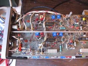
During testing of the “B” trigger circuit I tried triggering on the “B” trigger external input. This is something that I had never had a need to try since I owned the scope, so I wasn’t sure about how it would work. I failed to be able to trigger from it. After replacing the “B” trigger chip, I investigated further and realized that it wasn’t connected to the trigger board and another wire was in the location that it was supposed to be soldered to. Immediately, I realized that I had reconnected a wire incorrectly when putting the trigger board back into the chassis. This was the lone red wire in the image shown below.

Trigger Card

Trigger Card

Fortunately I had this picture that I took before taking it apart that showed where it was supposed to run to. I moved that wire and connected the “B” external trigger input and now the “B” external trigger worked. Thank heaven I took those pictures.

The second “issue” was a concern that when intensity is turned all the way up, a “dot” can be see on the screen even when the scope wasn’t triggering. I reviewed the the service manual, and found that the intensity circuit is additive, so this was possibly normal. I checked voltages in this section and a few other items and everything seemed close to spec. Finally, following service manual instructions, I adjusted the CRT bias down just a bit. After I couldn’t find any issue with the circuit, I have come to the conclusion that the design is working properly.

At this point, I think the Tektronix 465 is working fine in all respects. I’ll finish this series with one final posting recapping some things I learned during this adventure.

To be continued…

Tektronix 465 repair – part VII

Sorry about the delay in getting this posting up. It was delayed while I waited for a replacement part to ship from Canada. It has now arrived so I can continue the Saga.

If you haven’t been following my blog, you should go back to the first post of this series, in order to get caught up. I had everything working, except for the “B” trigger slope control.

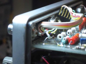
At this point, I decided to reconnect the external trigger input. I wasn’t quite sure how it was connected. Fortunately, I had taken a photograph of the connection before disassembly.

External Trigger Wiring

External Trigger Wiring

Though the picture wasn’t in focus, it was good enough for the purpose and I was able to reconnect the external trigger and test it successfully.

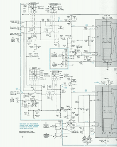
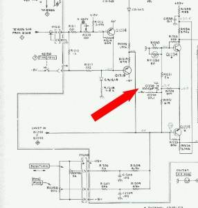
The slope control is fairly simple in function. It provides an basic input to the trigger amplifier chip, as can be seen in the schematic.

Trigger Input Schematic

Trigger Input Schematic

The “B” trigger and “A” trigger circuit are very similar. I was able to verify operation of the slope switch and the input to trigger amp chip by comparing the two circuits. After finding no difference, I decided to swap chips. Sure enough, now the “A” trigger was stuck triggering on down slope and “B” trigger now worked on either slope. The problem was a bad trigger chip.

Trigger Card

Trigger Card

The difficulty with finding a new one, is that this is a custom Tektronix chip. After finding several expensive sources on the internet, I was able to negotiate a deal with someone who was selling the entire trigger board. It took a while before I recieved the new chip and was able to install and test it. After installing, both triggers now worked on both slopes, and my Tek 465 was running sweeter than ever.

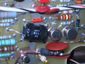
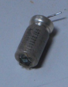
Do you remember, the 4.7uF capacitor that I had hacked in place of the bad 10uF capacitor? Before closing up the the scope, I needed to find a proper replacement. In a nearby shop, I found a radial 10uF electrolyic capacitor that I figured that I would be able to substitute for the original axial capacitor. This one had a 25 volt voltage rating, so I figured that it would last longer than the original, which was only rated at 10 volts. First, I removed the temporary 4.7uF capacitor. I bent the ground lead over on the new radial capacitor so it ran parallel to the body. I used a couple of short pieces of shrink wrap to hold the lead in that position. I then cut the leads to proper length and soldered the replacement capacitor in place.

Replacement Cap

Replacement Cap

There were two more things about this scope that bothered me, that I haven’t mentioned, yet. One just came to light during the testing of the trigger repair and the other has been a concern since I owned the scope.

To be continued…

6502 memory test gotcha – 6502 cheat sheet error

One of the more popular programs that I’ve written is this 6502 memory test. One person using this test to checkout his Mimeo, recently discovered that it doesn’t work with his early white 6502. Turns out that that particular 6502 is a nice collectors piece, without a functioning ROR instruction. I used the ROR instruction at the end of the third test, so the program hangs when run on an early 6502 with the missing ROR functionality.

;
;
; all test 2 passes complete – prepase for test 3
;
LDA #$7F
BNE NX_TEST ;always branch

CHK_TEST3 ;floating zeros in progress or done
CPY #3
BNE CHK_TEST4
;
; pass of test 3 complete – 8 passes in all with 0 in each bit position
;
SEC
ROR TEST_PATRN ; rotate right – Carry to MSB, LSB to Carry
BCS NX_PASS2 ; keep going until zero bit reaches carry

I haven’t checked it, but I think the following code will accomplish the same basic test without using the ROR instruction.

;
;
; all test 2 passes complete – prepase for test 3
;
LDA #$FE
BNE NX_TEST ;always branch

CHK_TEST3 ;floating zeros in progress or done
CPY #3
BNE CHK_TEST4
;
; pass of test 3 complete – 8 passes in all with 0 in each bit position
;
SEC
ROL TEST_PATRN ; rotate left – MSB TO Carry, LSB = Carry
BCS NX_PASS2 ; keep going until zero bit reaches carry

I recently discovered that my 6502 cheat sheet has an egregious error. The ROL and ROR instructions move the Carry bit into the LSB and MSB (respectively), not the MSB and LSB. In other words the instructions are rotate through carry instructions.

I’m not sure how I managed to mess this one up or why it took so long for me to notice this or why no one else noticed it. Perhaps the functionality of these instructions are so well known that most people don’t need to refer to a cheat sheet to understand functionality. Clearly, I knew how they worked (or were supposed to work in the case of the early chips) when I wrote the 6502 memory test.

Tektronix 465 repair – part VI

If you haven’t been following my blog, you should go back to the first post of this series, in order to get caught up. At this point, I have found the cause of the missing horizontal sweep and the scope was working as well as it did prior to the coffee spill. I still had the two pre-existing issues and since I was gaining familiarity with the scope, I decided to pursue those issues.

First thing to attack was the horizontal position control. This was fixed using essentially the same repair process as the trigger “A” control. There were a few differences. The horizontal position control is made up two potentiometers, instead of a potentiometer and a switch. The coarse potentiometer is 0-5K ohm pot and the fine is 0-50K ohm pot. This circuit can be seen in the lower left corner of the schematic showing the 1000 uF cap that was discussed in a previous post.

Bad Cap on Schematic

Bad Cap on Schematic

Testing with my DMM showed issues with both of them. Disassembly was easy, as the unit is held together with small machine screws and nuts. To ensure correct re-assembly, I took a couple of digital photos before taking it apart.

Horizontal Position Control

Horizontal Position Control

Once, disassembled, I flushed both pots with isopropyl alcohol a few times and worked the wiper back and forth. Testing with a DMM indicated that the correct behavior was restored with this simple cleaning. Re-installation was uneventful and testing showed that these position controls worked like they were supposed to.

Now I was really making progress. Ever since I first purchased the scope, these controls have never worked quite right.

The trigger “B” slope switch still wasn’t working – maybe I could also fix that. If I succeeded, I’d have every function working as designed for the first time since I’ve owned this tool.

to be continued…

Tektronix 465 repair – part V

If you haven’t been following my blog, you should go back to the first post of this series, in order to get caught up. At this point, I’ve disassembled and cleaned all the spilt coffee from the machine, repaired a trigger control, and replaced a bad electrolytic cap with a temporary substitute. However the machine still didn’t exhibit a horizontal trace. The -8 volt supply was showing it was shorted to ground. I thought that this was due to some problem in the horizontal timebase/sweep circuit.

At this point, I decided to try to further isolate the problem by disconnecting a number of components from the bottom (interface) board. This was quite easy to do, as I had already done this as part of the disassembly process of the trigger and timebase boards. I knew that the system wouldn’t work, this way, but I could check to see if the problem with -8 volts was on the bottom (interface) board or some other board. I unplugged whatever I could from the interface board and powered on the unit. At this point, -8 volts showed as correct, so I started plugging things back in, starting with the trigger control that I had fixed way back in part II of this series. Sure, enough -8 volts went back to ground and scope appeared to have horizontal sweep again.

Duh – my problem was with the repair I had made, and wasn’t due to something else that failed. I did notice all along, that the stop at one end of the rotation didn’t seem quite right. Before removing the switch I checked and sure enough, it seemed shorted to ground. I removed the switch and checked it out. After removing it, everything seemed fine and I could find no short in the switch and the glitch in the rotation disappeared. I reinstalled it and found no short and rotation continued to behave normally. I could only guess that the first time that I installed the switch, that I hadn’t put the index correctly in the slot. When tightened down, the shell had deformed and caused an internal short and also the problem with rotation.

At this point, I figured that this was likely to be the last time that I had the timebase and trigger boards disconnected. As I reconnected everything, I cleaned any soldering residue off the connections that I had to solder to remove or reattach. I did this with isopropyl alcohol applied with a small, stiff, paint brush. I scrubbed the residue until it dissolved and cleaned it up with a paper towel.

I reconnected everything, except the external trigger input, and powered up. The trigger input connected to a large area of copper that required a lot of heat, so I decided to do this later on. Besides, I didn’t quite remember how it was connected. Once I connected everything else, I powered up. This time, my treasured Tektronix 465 seemed to behave correctly. I connected scope probes to both inputs and to the calibration output and got good waveforms and the “A” trigger control worked like it was supposed to.

However, trigger “B” still would only trigger on the downslope and the horizontal position control had the same jerky operation as before. By now, I was getting more comfortable with working with this scope, so I decided that I would investigate those issues before reconnecting the external trigger input and putting it all back together.

to be continued…

Tektronix 465 repair – part IV

If you haven’t been following my blog, you should go back the to first post of this series, in order to get caught up. At this point I have the trigger and horizontal control board out of the scope, looking for a problem with the -8 volt power supply.

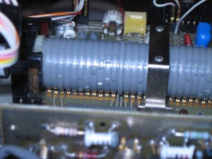
After examining horizontal control board, I’m kind of surprised to see that there isn’t a whole lot circuitry on it. I’m sure that was by design, because, for the most part, this board is unaccessible when installed. It mostly contains the horizontal sweep control, which is hidden under a metal shield. Curious about it, I unbolted the shield to see what was underneath. What I found is a masterpiece in electro-mechanical engineering. I’ve always wondered why I didn’t ever have trouble with the time base control on my 465 and now, I knew why. If the bandswitch control on my Kenwood 530S was built this way, I’m sure I would have never needed to fix it.

Horizontal Timebase Control

Horizontal Timebase Control

Now that I had this board out, I cleaned the switches that were so sticky from the spilt coffee. I also looked for leakage down into the circuit, but found no sign of any coffee beyond the buttons that extended out the front the machine. Since I had so many controls removed from the front panel, I cleaned it up as much as possible. The lack of components and signs of coffee made me think that the problem with -8 volts was not on this timing control board.

I kind of stepped back and took an overall look at the machine. It was at this point, that I noticed a bad capacitor on the bottom (interface) board. One lead had fallen off and in general this capacitor looked like it had seen better days.

Bad Cap

Bad Cap

I looked this capacitor on the schematic and it didn’t seem to have a big role, but it was near to the -8 volt rail, so there was slight hope that this could be the root cause of my issue. It was a 1000uF electrolytic cap, which was rated for 10 volts.

Bad Cap on Schematic

Bad Cap on Schematic

I removed the cap and found a 470uF radial cap in my stash, which was the closest thing in value to the original that I had. I soldered it in place as a temporary patch to see if it would help. I put the cover back on the timebase switch, I plugged in the two boards I had pulled and reconnected most of the wires that I had disconnected to see if this replacement cap would solve the issue.

I powered up and the scope had no horizontal trace, exactly the same as prior to the capacitor replacement.

to be continued…

Tektronix 465 repair part III

My previous posts describe a little of the repair history of my Tektronix 465 and events leading up to this blog entry. At this point, after a repair of the trigger “A” control, the scope now would not display a proper trace. If brightness was turned up all the way, it would display only a tiny dot at the center of the screen.

Now I had to debug a new problem. Since the scope was in a useless state, there was no question about stepping up to the plate and moving into full debug mode. First thing I did was do some web searches to locate and downloaded the service manual.

An important early step in debugging sessions of this sort is to check system voltages. According to the service manual, the voltage test points are on the bottom board. With the unit on it’s side I checked the voltages and found that the -8 volt rail was near ground which was a big problem. Next step was to check the power supply electronics. After at least an hour or two of probing components and reviewing the schematics, I couldn’t find any obvious issue with the -8 volt power supply. Something else must be holding the -8 rail to or near ground.

The service manual gives some suggestions for isolating the -8 rail from horizontal amplifier circuit or the CRT circuit by lifting legs on some components. Since the CRT seemed fine, but the horizontal amp definitely wasn’t working, I started by isolating the horizontal amp. It turns out that there is a jumper designed for this purpose. I started by lifting one one leg of the jumper and sure enough, -8 volts returned to it’s proper value. So this must have meant that the problem with -8 volts was with the horizontal amplifier.

Most of the horizontal amplifier is on the bottom board, the same board as the power supply. I just needed to shift my probing to a different corner of the board. Since there was no obvious burn or failed component in that section, I started probing to find a defective component. My probing involved looking for a capacitor, resistor, diode or transistor that wasn’t operating correctly. Capacitors are checked for value and shorts. Diodes and transistors are checked with the diode test function of my DMM. Resistors are checked for value. The main complication is that the components are in circuit, and other components in the circuit can affect readings. After several hours of probing components and checking things while powered on I could find nothing that would indicate a problem that would short -8 volts to ground.

At this point, I went back to my original thought that spilt coffee might have worked it’s way into the system and caused some problem, like it did with the trigger control. Moving deeping into the horizontal timing system looked like a daunting task, but I figured that I needed to proceed. After all, a broken scope was no good to me.
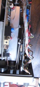
465 top view - horizontal control

465 top view – horizontal control


Top view of trigger and timebase boards. Note the writing harness and individual wires that must be disconnected to remove these boards.

The service manual has a section that describes the steps to remove the trigger and timebase boards. There are wires that need to be disconnected or unsoldered to do this. At this point, I got out a digital camera and took some pictures of wiring that I thought I might forget how to reconnect. Some of pictures used in this blog were taken at that time. I also made some handwritten notes showing how the wiring needed to be reconnected.
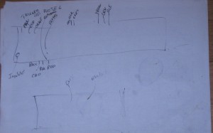
465 Wiring Notes

465 Wiring Notes

Following the instructions in the service manual as best I could, I removed the trigger and timebase boards. Some instructions in the service manual didn’t exactly match my particular system, but most of them did. Having the manual was a great benefit in removing these two boards.

to be continued…

Tektronix 465 repair part II

My previous post describes a little of the repair history of my Tektronix 465 and the recent failure of the trigger “A” level control after a spilt coffee event.

So now I had a Tektronix 465 that was completely useless. I figured that the coffee had penetrated into the trigger “A” potentiometer and caused an open or short in it. My experience with the trigger “B” pot indicated that I should be able to open it up and clean it out without too much difficulty. Whether I could restore it to proper functionality was another matter.

The 465 is easy to get into. Unplug the unit and remove the 6 screws on the back, 4 of which hold the feet on. Then slide the chassis out of the enclosure. The trigger controls are on exposed on the right side of the chassis. Both trigger controls can be seen on the left side of this image. This image also shows why I have been a bit nervous about troubleshooting this unit. A lot of discrete logic and individual wires running around doing mysterious things.

Trigger Card

Trigger Card

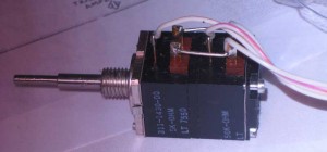
The controls have dual functions in one unit. On the back is the slope switch, which is a simple on/off switch. On the front side is a 10K potentiometer. Removing the control from the chassis is easy. Use an allen wrench to loosen the screws holding on the knobs and remove them. Use a wrench to remove the nut and washer holding the control to the front panel. Unplug the wiring harness and you should be able to remove the control from the chassis.

Once removed, I tested the pot by using an DMM on ohms setting to check for dead spots or shorts. A 10K pot should show a gradual/steady progression as you rotate the control. Testing showed that this control clearly had issues as it reported open circuits in various postions. I decided to open it up and clean it out and see if I could restore proper operation.

I opened the control by gently bending back the tabs holding the control together. These are the tabs at the front of the control. Note that one of these tabs is not bent over by the factory. This tab is used to index the control to the front panel. This tab should not be bent back over, when reassembling the control. Don’t touch the ones at the back of the control, unless the switch part of the control is really messed up and you need to get in there to straighten it out. You have to be gentle bending these tabs back, as they are not intended to be opened. The metal will fail if you have to do this more than a couple of times or you are not careful with them. Once opened, the control will come apart. Be aware that the hardest part of putting it back together will be getting the switch portion properly engaged as you put everything back together. Try to pay attention to how the switch mechanism is set up, before everything comes apart.

I used a cleaning process that is very similar to what I have used on Datanetics mechanical keyswitches. I simply flooded the mechanism with isopropyl alcohol and rotated the wiper. After doing this a couple of times, I tested again with the DMM. After doing this, it appeared that it was operating correctly. I let it dry overnight and retested in the morning before reassembling the control.

I installed the control in the chassis and turned on the scope. Oh-no, now I didn’t get a trace. No matter what controls I changed, the only sign of a trace, was a small dot in the center of the screen. This dot could only be seen, if I turned the brightness fully up.

My first thought was that the coffee had migrated to somewhere else and now messed up the horizontal control circuit.

to be continued…