Dummy Load
A dummy load is an antenna replacement that doesn’t actually transmit. It is used to tune up and check out RF transmitters. I needed to build one to check out my vintage HAM transmitter before actually getting on the air. The last thing I want to do as a new HAM, is to transmit a poor signal. The design of a basic dummy load is pretty simple and is composed of two main components.
A source of impedance, that is designed to act like an antenna
A way to dissipate the heat that the source of impedance creates
Some loads may also have additional capability to measure power and other important parameters of your transmitters signal.
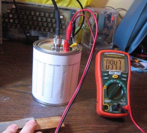
I could have purchased a dummy load, but like many things in my life, I decided to do things the hard way and build my own. Several months ago, I started work on this project. I found a simple design on Ken, K4EAA’s, website. This design utilizes an array of resistors that combined together produce an equivalent to the 50 ohm load that a well tuned antenna would generate. I proceeded to procure the necessary components. I purchased the resister’s that Ken sold, a paint can at the local hardware store and a few other components at a couple of different places.
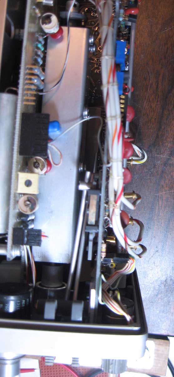
My load is almost the same as Ken’s, except that I put the “hot” side on top and the ground side on the bottom side of the can. I figured that the hot side would be a little less likely to short out to the side of the can, if built that way.
An option with this unit, is adding a couple of binding posts that can be used to measure the power being consumed. The extra components needed are only a diode and a capacitor. Ken’s unit was built with 2 1N4148 diodes, but he provided a BAV21 with the resistor set. One key parameter of the diodes is the max reverse voltage. The HF output of a 100 watt transmitter, like my Kenwood, can be over 100 volts. The BAV21 has a max reverse voltage of 200 volts. The 1n4148 spec lists it as 100 volts, which is why Ken put two in series.
Anyway, after constructing the dummy load, the fun really began. Before installing the capacitor, I attached my radio to the dummy load and tried out the basic load functionality. It worked perfectly, with my SWR meter showing an SWR barely over 1. Next I attached a 250V, .001 uF capacitor that I happened to have left over from a previous project. Here is where things started going badly. The SWR went off the meter with the cap attached. I tried several things, checked how I had mounted the diode and binding posts and couldn’t see anything seriously wrong. After a little while, I gave up and left the capacitor off. I figured I would revisit the project in the future.
Fast forward to this last weekend. I’m getting ready to go on the air, and figured that I needed to check out my transmitter again. After successfully checking out the transmitter, I decided I needed to take another look at getting the power measurement feature of the dummy load working.
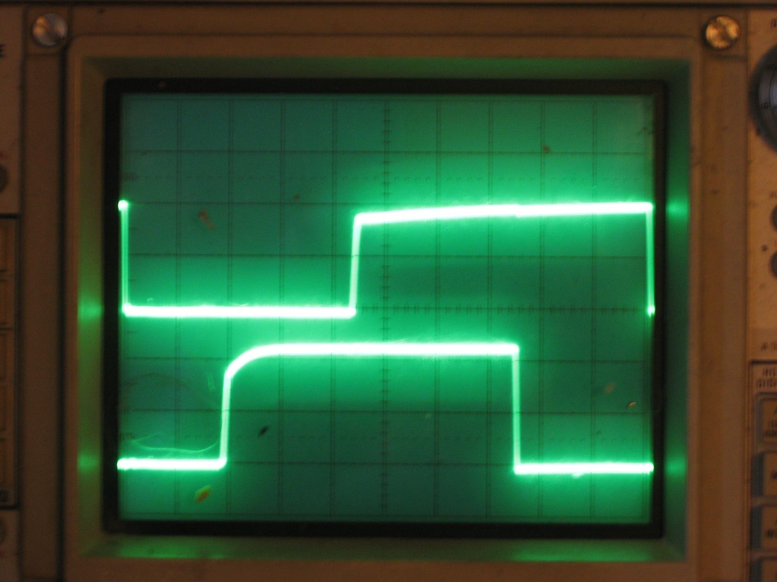
This time, I had my oscilloscope ready, and was going to investigate more exhaustively. First, I tried a lower value capacitor to no effect. After hooking up the scope, I found the signal on the binding posts looked like a miniature version of 100 volt sine wave that the transmitter was sending. The signal between the binding posts was about 10 volts, peak to peak. After quite a bit of messing around with other capacitors and measuring various aspects of the simple circuit, I figured I’d pull up the BAV-21 data sheet.
What I found, pretty much indicated that a BAV-21 probably wasn’t the right diode for the job. All capacitors have a parameter called reverse recovery time. This is the amount of time for the diode to switch from conducting to not conducting in the reverse direction. Well the data sheet value for a BAV-21 is 50 nano-seconds for their standard test conditions. I did a quick calculation. What the calculation showed me is that when exposed to a 20 MHZ sine wave, it will never completely shut off. Though I was testing at around 10 MHZ, it seems that the selection of that part probably wasn’t ideal.
I have a number of 1N914 diodes around and pulled up the data sheet. Reverse recovery was listed at 4 nano-seconds, which means it should work much better. The down side is that the max reverse voltage is only 100 volts. I also found out that the 1N4148 that Ken used has the exact same specs. In fact, these days, they are considered the same part. I figured I could do a quick test with a single 1N914, since the voltages I measured were around 100 volts. I figured that it was near the limit, but if I didn’t run it too hard, it should survive.
I hooked everything back up. The SWR was now perfect, but the measurement values on the binding posts are still bad. Now, I’m really confused and decide to do an LTspice model of this simple circuit.
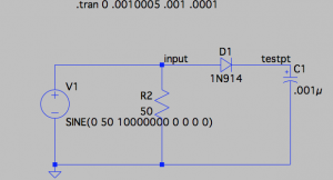
Spice Dummy Load Model
I learned a few things doing the simulation.
The circuit should work fine
A larger cap will not give any better results than .001uF
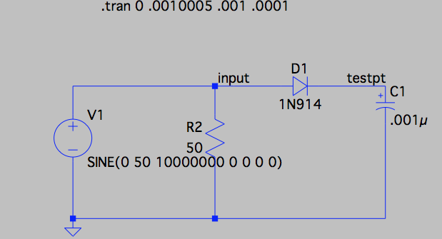
Spice Dummy Load Model
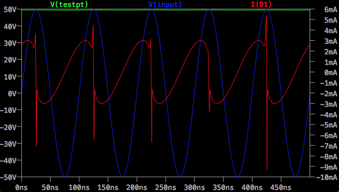
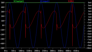
The blue line is a 100 volt peak to peak transmitter signal. The green line at the top should be the value at the binding posts. The red line shows the current across the diode. The sharp negative spike in current is the reverse recovery time. I did a brief search, and I couldn’t find a model for the BAV-21. Would be interesting to see what a simulation of that diode looked like.
After doing this analysis, I scratched my head some more, and did some more checking connections and signals. Finally, I determined that the 1N914 diode was dead. I must have exceeded the reverse voltage rating and fried it. I should have put two of them in series, like Ken did. I replaced the burned out one with 2 1N4148 diodes in series and everything started working perfectly.
The chart on the side of the can, was created by measuring the resistance of the load and the diode drop of the two 1N4148 diodes. I created a spreadsheet that calculated power for each possible voltage measurement. I printed it out, cut it to size and glued to the side of the can.
I’m still a bit surprised that several sites list the BAV-21 diode as the correct part for this job. Dummy loads have been around for decades. You would think that errors like this would be corrected by now.